


![]()
The pic0rick is the current recommended board in the un0rick family. It replaces the FPGA-based designs with an RP2040/RP2350 microcontroller, delivering comparable ultrasound acquisition performance at a fraction of the cost and complexity — with no FPGA toolchains or specialized hardware knowledge required.
New to the project? Start with the Getting started guide for a step-by-step walkthrough from unboxing to your first echo.
Specifications
| Parameter | Value |
|---|---|
| Microcontroller | RP2040 (dual-core Cortex-M0+, 133 MHz). RP2350 also supported |
| ADC | 60 Msps, 10-bit resolution |
| TGC amplifier | AD8331 — 7.5 dB to 55.5 dB variable gain |
| TGC control | MCP4812 SPI DAC |
| Pulse generation | Three-level pulser via MD1210 + TC6320 (on pulser PMOD board) |
| Pulse voltage | +-25 V (via HV generation board) |
| Input protection | HV clipping on receive path |
| PMOD connectors | 1x single (pulser), 1x double (VGA, MUX, PSRAM, or custom) |
| Data interface | USB (serial) |
| PIO usage | PIO0: acquisition timing, PIO1: VGA output (when connected) |
| Power | USB bus powered |
| Design files | KiCad (open source) |
| Firmware | C/C++ for RP2040 — Arduino-like development environment |
| Certification | OSHWA open-source hardware certified as FR000023 |
System architecture
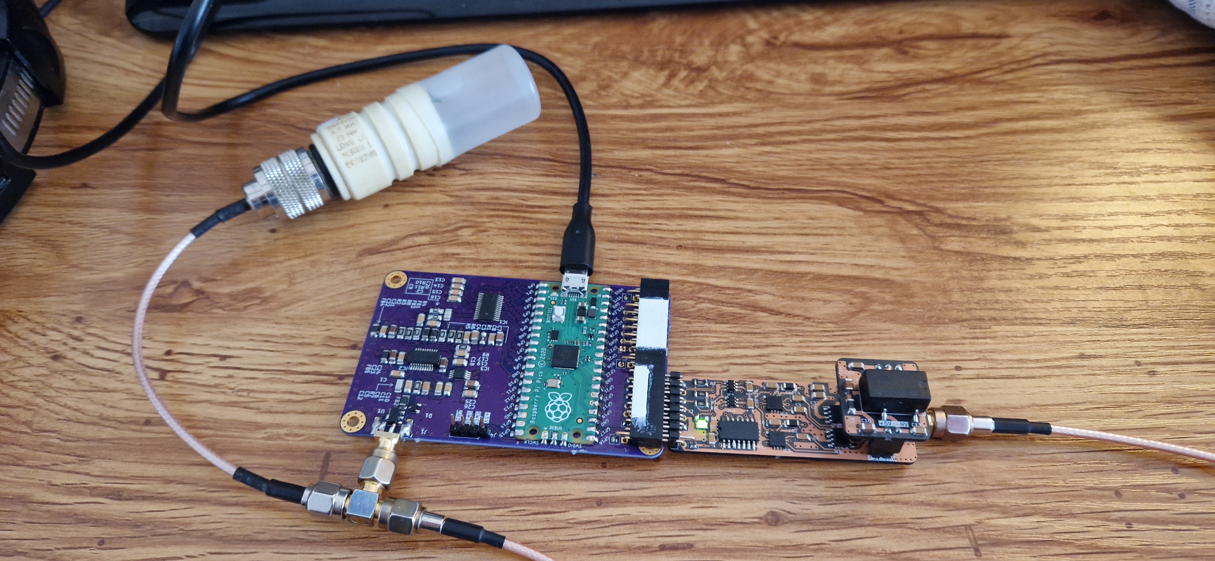
The pic0rick is a modular three-board system:
Main board — The core of the system. Contains the RP2040 microcontroller, the 60 Msps 10-bit ADC, the AD8331 TGC amplifier with SPI-controlled gain curve, and HV input protection on the receive path. The main board hosts both PMOD connectors and the USB interface.
Pulser board (single PMOD) — Generates the transmit pulse on behalf of the main board. Uses a pair of MD1210 + TC6320 to produce three-level pulses. Requires the HV board for high-voltage supply.
HV board — A simple +-25V generation board that plugs into the pulser board. Provides the high-voltage rail needed for pulse generation.
The signal chain works as follows:
RP2040 → PIO triggers pulse → Pulser board → Transducer → Echo returns
→ HV clipping (protection) → AD8331 TGC → 60 Msps ADC → RP2040 → USB → Computer
The RP2040’s two PIO units are used for precise timing: one drives the acquisition sequence (pulse trigger + ADC sampling), and the other can drive a VGA output for real-time visualization — leaving the two Cortex-M0+ cores free for your own application code.
How does it replace the FPGA?
Previous boards (un0rick, lit3rick) used a Lattice iCE40 FPGA for precise timing control of the pulse-echo sequence. The pic0rick achieves the same timing precision using the RP2040’s Programmable Input/Output (PIO) state machines. PIO programs run deterministically at the system clock rate, providing the sub-microsecond timing needed for ultrasound acquisition — without requiring HDL knowledge or FPGA synthesis tools.
This means you can modify the acquisition timing, pulse patterns, and sampling parameters by editing C code in a standard Arduino-like environment, rather than writing Verilog or VHDL and running a synthesis toolchain.
PMOD extensions
The double PMOD connector supports several expansion boards:
| Extension | Function |
|---|---|
| VGA output | Real-time display of acquisitions on a VGA monitor — uses PIO1 |
| MUX board | Multiplexer for driving multiple transducers — enables array imaging and synthetic aperture |
| PSRAM | Additional memory for longer acquisition buffers |
| Custom | The PMOD pinout is documented — design your own extensions |
Note: the PMOD headers include a 5V rail in addition to the standard signals, so they are not strictly PMOD-compliant — but this allows powering more demanding extension boards directly.
For more details, see the Extensions page.
Board comparison
How does the pic0rick compare to the older un0rick-family boards?
| pic0rick | un0rick | lit3rick | lit3-32 | |
|---|---|---|---|---|
| Status | Active | Legacy | Legacy | Legacy |
| Years | 2024–now | 2018–2025 | 2020–2024 | 2021–2024 |
| Controller | RP2040 / RP2350 | iCE40 HX4K/HX8K | iCE40 UP5K | iCE40 UP5K |
| Type | Microcontroller | FPGA | FPGA | FPGA |
| ADC speed | 60 Msps | Up to 64 Msps | Up to 64 Msps | Up to 64 Msps |
| ADC resolution | 10-bit | 10-bit | 10-bit | 10-bit |
| TGC amplifier | AD8331 (48 dB range) | AD8331 (48 dB range) | AD8331 (48 dB range) | AD8332 (92 dB range) |
| Onboard HV | No (separate board) | Yes | No | No |
| Form factor | Compact + PMODs | Large single board | RPi pHAT | RPi pHAT |
| Programming | C/C++ (Arduino-like) | Verilog + Python | Verilog + Python | Verilog + Python |
| FPGA required | No | Yes | Yes | Yes |
| Extensible | PMOD connectors | Limited | RPi GPIO | RPi GPIO |
| Cost | Lowest | Medium | Low | Medium-high |
| Best for | New projects, education, fast prototyping | Users needing full FPGA flexibility | RPi-integrated setups | Weak signal detection (high gain) |
For new projects, we recommend the pic0rick unless you specifically need FPGA-level timing control or the 92 dB gain range of the lit3-32.
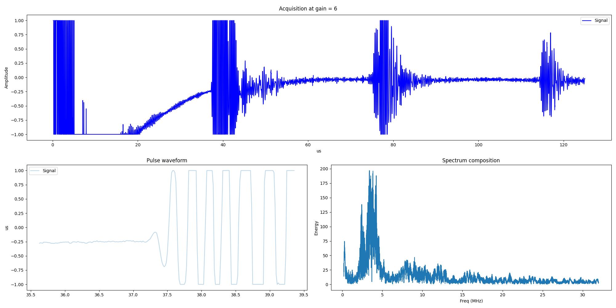
Example of acquisition
A typical acquisition looks like this — the large spike on the left is the transmit pulse, and the smaller peaks to the right are reflections from your target:
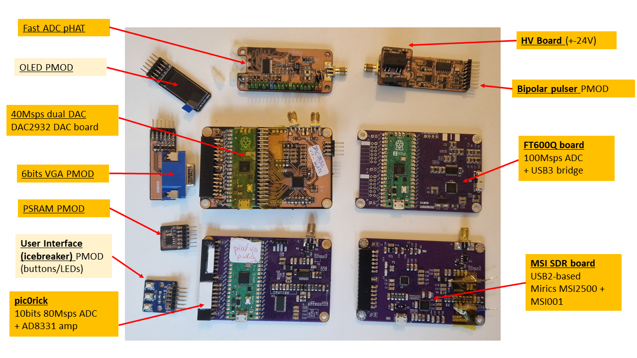
The pic0rick alongside older boards
Source files
All design files are open source:
- Hardware (KiCad): Main board, pulser board, HV board — in the pic0rick repository
- Firmware: RP2040 C/C++ source code — in the
software/directory - Documentation: Published under CC BY-SA 3.0
Get one
Thank you to
License
This work is based on three previous TAPR projects, the echOmods project, the un0rick project, and the lit3rick project — their boards are open hardware and software, developed with open-source elements as much as possible.
Copyright Luc Jonveaux ([email protected]) 2024
- The hardware is licensed under TAPR Open Hardware License (www.tapr.org/OHL)
- The software components are free software: you can redistribute it and/or modify it under the terms of the GNU General Public License as published by the Free Software Foundation, either version 3 of the License, or (at your option) any later version.
- The documentation is licensed under a Creative Commons Attribution-ShareAlike 3.0 Unported License.
Disclaimer
This project is distributed WITHOUT ANY EXPRESS OR IMPLIED WARRANTY, INCLUDING OF MERCHANTABILITY, SATISFACTORY QUALITY AND FITNESS FOR A PARTICULAR PURPOSE.