In the 1980s, if you wanted your computer to do floating-point calculations faster, you could buy the Intel 8087 floating-point coprocessor chip. Plugging it into your IBM PC would make operations up to 100 times faster, a big boost for spreadsheets and other number-crunching applications. The 8087 uses complicated algorithms to compute trigonometric, logarithmic, and exponential functions. These algorithms are implemented inside the chip in microcode. I'm part of a group that is reverse-engineering this microcode. In this post, I examine the 49 types of conditional tests that the 8087's microcode uses inside its algorithms. Some conditions are simple, such as checking if a number is zero or negative, while others are specialized, such as determining what direction to round a number.
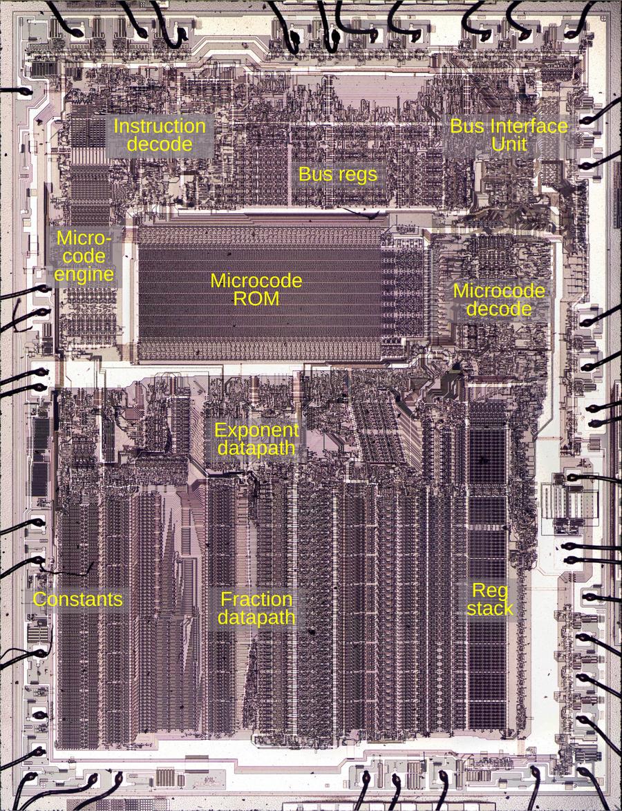
To explore the 8087's circuitry, I opened up an 8087 chip and took numerous photos of the silicon die with a microscope. Around the edges of the die, you can see the hair-thin bond wires that connect the chip to its 40 external pins. The complex patterns on the die are formed by its metal wiring, as well as the polysilicon and silicon underneath. The bottom half of the chip is the "datapath", the circuitry that performs calculations on 80-bit floating point values. At the left of the datapath, a constant ROM holds important constants such as π. At the right are the eight registers that the programmer uses to hold floating-point values; in an unusual design decision, these registers are arranged as a stack.

Die of the Intel 8087 floating point unit chip, with main functional blocks labeled. The die is 5mm×6mm. Click for a larger image.
The chip's instructions are defined by the large microcode ROM in the middle. To execute a floating-point instruction, the 8087 decodes the instruction and the microcode engine starts executing the appropriate micro-instructions from the microcode ROM. The microcode decode circuitry to the right of the ROM generates the appropriate control signals from each micro-instruction.1 The bus registers and control circuitry handle interactions with the main 8086 processor and the rest of the system.
The 8087's microcode
Executing an 8087 instruction such as arctan requires hundreds of internal steps to compute the result. These steps are implemented in microcode with micro-instructions specifying each step of the algorithm. (Keep in mind the difference between the assembly language instructions used by a programmer and the undocumented low-level micro-instructions used internally by the chip.) The microcode ROM holds 1648 micro-instructions, implementing the 8087's instruction set. Each micro-instruction is 16 bits long and performs a simple operation such as moving data inside the chip, adding two values, or shifting data. I'm working with the "Opcode Collective" to reverse engineer the micro-instructions and fully understand the microcode (link).
The microcode engine (below) controls the execution of micro-instructions, acting as the mini-CPU inside the 8087. Specifically, it generates an 11-bit micro-address, the address of a micro-instruction in the ROM. The microcode engine implements jumps, subroutine calls, and returns within the microcode. These jumps, subroutine calls, and returns are all conditional; the microcode engine will either perform the operation or skip it, depending on the value of a specified condition.

The microcode engine. In this image, the metal is removed, showing the underlying silicon and polysilicon.
I'll write more about the microcode engine later, but I'll give an overview here. At the top, the Instruction Decode PLA2 decodes an 8087 instruction to determine the starting address in microcode. Below that, the Jump PLA holds microcode addresses for jumps and subroutine calls. Below this, six 11-bit registers implement the microcode stack, allowing six levels of subroutine calls inside the microcode. (Note that this stack is completely different from the 8087's register stack that holds eight floating-point values.) The stack registers have associated read/write circuitry. The incrementer adds one to the micro-address to step through the code. The engine also implements relative jumps, using an adder to add an offset to the current location. At the bottom, the address latch and drivers boost the 11-bit address output and send it to the microcode ROM.
Selecting a condition
A micro-instruction can say "jump ahead 5 micro-instructions if a register is zero" and the microcode engine will either perform the jump or ignore it, based on the register value. In the circuitry, the condition causes the microcode engine to either perform the jump or block the jump. But how does the hardware select one condition out of the large set of conditions?
Six bits of the micro-instruction can specify one of 64 conditions. A circuit similar to the idealized diagram below selects the specified condition. The key component is a multiplexer, represented by a trapezoid below. A multiplexer is a simple circuit that selects one of its four inputs. By arranging multiplexers in a tree, one of the 64 conditions on the left is selected and becomes the output, passed to the microcode engine.

A tree of multiplexers selects one of the conditions. This diagram is simplified.
For example, if bits J and K of the microcode are 00, the rightmost multiplexer will select the first input. If bits LM are 01, the middle multiplexer will select the second input, and if bits NO are 10, the left multiplexer will select its third input. The result is that condition 06 will pass through the tree and become the output.3 By changing the bits that control the multiplexers, any of the inputs can be used. (We've arbitrarily given the 16 microcode bits the letter names A through P.)
Physically, the conditions come from locations scattered across the die. For instance, conditions involving the opcode come from the instruction decoding part of the chip, while conditions involving a register are evaluated next to the register. It would be inefficient to run 64 wires for all the conditions to the microcode engine. The tree-based approach reduces the wiring since the "leaf" multiplexers can be located near the associated condition circuitry. Thus, only one wire needs to travel a long distance rather than multiple wires. In other words, the condition selection circuitry is distributed across the chip instead of being implemented as a centralized module.
Because the conditions don't always fall into groups of four, the actual implementation is slightly different from the idealized diagram above. In particular, the top-level multiplexer has five inputs, rather than four.4 Other multiplexers don't use all four inputs. This provides a better match between the physical locations of the condition circuits and the multiplexers. In total, 49 of the possible 64 conditions are implemented in the 8087.
The circuit that selects one of the four conditions is called a multiplexer. It is constructed from pass transistors, transistors that are configured to either pass a signal through or block it. To operate the multiplexer, one of the select lines is energized, turning on the corresponding pass transistor. This allows the selected input to pass through the transistor to the output, while the other inputs are blocked.

A 4-1 multiplexer, constructed from four pass transistors.
The diagram below shows how a multiplexer appears on the die. The pinkish regions are doped silicon. The white lines are polysilicon wires. When polysilicon crosses over doped silicon, a transistor is formed. On the left is a four-way multiplexer, constructed from four pass transistors. It takes inputs (black) for four conditions, numbered 38, 39, 3a, and 3b. There are four control signals (red) corresponding to the four combinations of bits N and O. One of the inputs will pass through a transistor to the output, selected by the active control signal. The right half contains the logic (four NOR gates and two inverters) to generate the control signals from the microcode bits. (Metal lines run horizontally from the logic to the control signal contacts, but I dissolved the metal for this photo.) Each multiplexer in the 8087 has a completely different layout, manually optimized based on the location of the signals and surrounding circuitry. Although the circuit for a multiplexer is regular (four transistors in parallel), the physical layout looks somewhat chaotic.

Multiplexers as they appear on the die. The metal layer has been removed to show the polysilicon and silicon. The "tie-die" patterns are due to thin-film effects where the oxide layer wasn't completely removed.
The 8087 uses pass transistors for many circuits, not just multiplexers. Circuits with pass transistors are different from regular logic gates because the pass transistors provide no amplification. Instead, signals get weaker as they go through pass transistors. To solve this problem, inverters or buffers are inserted into the condition tree to boost signals; they are omitted from the diagram above.
The conditions
Of the 8087's 49 different conditions, some are widely used in the microcode, while others are designed for a specific purpose and are only used once. The full set of conditions is described in a footnote7 but I'll give some highlights here.
Fifteen conditions examine the bits of the current instruction's opcode. This allows one microcode routine to handle a group of similar instructions and then change behavior based on the specific instruction. For example, conditions test if the instruction is multiplication, if the instruction is an FILD/FIST (integer load or store), or if the bottom bit of the opcode is set.5
The 8087 has three temporary registers—tmpA, tmpB, and tmpC—that hold values during computation. Various conditions examine the values in the tmpA and tmpB registers.6 In particular, the 8087 uses an interesting way to store numbers internally: each 80-bit floating-point value also has two "tag" bits. These bits are mostly invisible to the programmer and can be thought of as metadata. The tag bits indicate if a register is empty, contains zero, contains a "normal" number, or contains a special value such as NaN (Not a Number) or infinity. The 8087 uses the tag bits to optimize operations. The tags also detect stack overflow (storing to a non-empty stack register) or stack underflow (reading from an empty stack register).
Other conditions are highly specialized. For instance, one condition looks at the rounding mode setting and the sign of the value to determine if the value should be rounded up or down. Other conditions deal with exceptions such as numbers that are too small (i.e. denormalized) or numbers that lose precision. Another condition tests if two values have the same sign or not. Yet another condition tests if two values have the same sign or not, but inverts the result if the current instruction is subtraction. The simplest condition is simply "true", allowing an unconditional branch.
For flexibility, conditions can be "flipped", either jumping if the condition is true or jumping if the condition is false. This is controlled by bit P of the microcode. In the circuitry, this is implemented by a gate that XORs the P bit with the condition. The result is that the state of the condition is flipped if bit P is set.
For a concrete example of how conditions are used, consider the
microcode routine
that implements FCHS and FABS, the
instructions to change the sign and compute the absolute value, respectively.
These operations are almost the same (toggling the sign bit versus clearing the sign bit), so the same
microcode routine handles both instructions, with a jump instruction to handle the difference.
The FABS and FCHS instructions were designed with identical opcodes,
except that the bottom bit is set for FABS.
Thus, the microcode routine uses a condition that tests the bottom bit, allowing the routine to branch and
change its behavior for FABS vs FCHS.
Looking at the relevant micro-instruction, it has the hex value
0xc094, or in binary 110 000001 001010 0.
The first three bits (ABC=110) specify the relative jump operation (100 would jump to a fixed target and 101 would
perform a subroutine call.)
Bits D through I (000010) indicate the amount of the jump (+`).
Bits J through O (001010, hex 0a) specify the condition to test, in this case, the last bit of the instruction opcode.
The final bit (P) would toggle the condition if set, (i.e. jump if false).
Thus, for FABS, the jump instruction will jump ahead one micro-instruction.
This has the effect of skipping the next micro-instruction, which sets the appropriate sign bit for
FCHS.
Conclusions
The 8087 performs floating-point operations much faster than the 8086 by using special hardware, optimized for floating-point. The condition code circuitry is one example of this: the 8087 can test a complicated condition in a single operation. However, these complicated conditions make it much harder to understand the microcode. But by a combination of examining the circuitry and looking at the micocode, we're making progress. Thanks to the members of the "Opcode Collective" for their hard work, especially Smartest Blob and Gloriouscow.
For updates, follow me on Bluesky (@righto.com), Mastodon (@[email protected]), or RSS.