One thing I remain fascinated by is the field-sequential color system. Essentially, unlike composite video, which sacrifices color depth in space, field sequential sacrifices color depth in time. But the specifics matter, and we have the specifics: the United States adopted such a system, but didn’t stick with it. So this article describes a nonexistent, alternate-world computer– what would an early mass-market 8-bit computer have looked like in a world where the field-sequential color system was in place?
Point of Divergence
Let’s look at the timeline of field-sequential color in the United States.
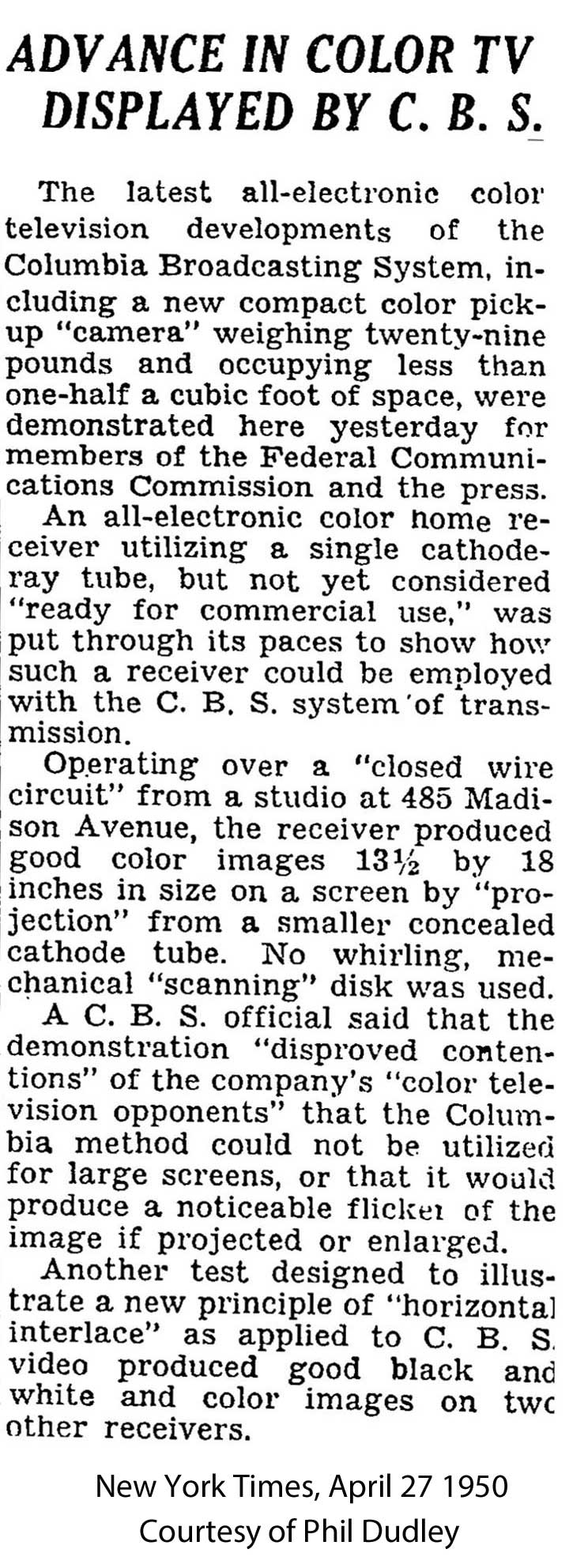
- January 12, 1950: CBS reveals their system to the public.
- October 11, 1950: Formal authorization of the field-sequential system
- October 17, 1950: RCA files a lawsuit against the FCC
- October 18, 1950: New York Times condemns incompatible system’s adoption
- November 1950: Public tests begin
- May 28, 1951: Supreme Court rules against RCA
- June 25, 1951: CBS begins full broadcasting in field-sequential color in NYC
- October 20, 1951: Color broadcasting ends
- March 26, 1953: CBS abandons their system
In alternate history, the “point of divergence” is the point where an alternate timeline (“ATL”) splits off from the original timeline (“OTL”). There is a very simple point of divergence for this project: avoid the Korean War. This, of course, would have huge effects on geopolitics, on the lives of people not killed in the war, their families, basically everyone in Korea, on the Cold War generally, and we’re just going to ignore all of that nonsense to focus on a niche computer industry difference. In this timeline, the 38th parallel holds.
Why is the Korean War relevant? Well, the southern invasion of the north began on June 25, 1950. UN forces landed at Inchon on September 15, 1950. And during the Korean War, the American National Production Agency wanted the end of color television to free up resources for the war effort; this is why things fizzled out so quickly in late 1951. The war ended (-ish) in July 27, 1953, by which point NBC had a “compatible color” system we all know and love raring to go. So we need to get rid of the Korean War to give CBS time to gain market share.
To be clear, compatible color is better than the CBS field-sequential system in basically every way. We are saddling this timeline with a weird spinning-disc system. But we are saving the lives of ~3 million people so who’s to say what is bad
The standard
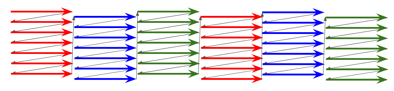
In broad strokes, CBS field-sequential color is interlaced in both lines, and in colors.

But to actually make something here, we’re going to need to look into the standard in more details than that. So I started with looking at US Patent 2,304,081, granted December 8, 1942, in the midst of World War 2. Unfortunately, this patent has a lot of nice diagrams, but is focused on the broad concept, not the specifics of the standard adopted in 1951.

Wikipedia cites a 1999 IEEE publication, which is behind a paywall. However, searching for the DOI did allow me to at least uncover this table:

And eventually I was able to get ahold of a copy of the paper in question. The first author is listed as Peter Goldmark, who, it’s worth noting, died in 1977. So this is seems to be a republish of an original paper from 1942. I notice that none of the tables apparently match the claimed characteristics of the CBS field-sequential system, but System 3 is the chosen one from the paper.
You might notice in the table above, there’s a distinction between “color frames”, “frames”, and “color pictures”. Terminology is a little clunky to the modern eye because we ended up with a system where every frame contains full color information. I’ll create the term “progressive color frame rate”; if you weren’t interlacing, what would be your rate of full-color frames? In NTSC, this is the same thing as the field rate. In field-sequential System 3, this takes three fields.
I was unable to find a description of how the blanking periods worked in System 3. However, frustratingly, despite being the main citation, System 3 is not the CBS color system that was adopted in 1951! The first citation I could find proving this was this 1951 Radio and Television News article, transcribed here. But yes, this was a 144Hz system! Presumably that adjustment was made after 1942.
Finally, I was able to get my hands on the Federal Register for October of 1950, wherein the linked PDF the color information starts on page 10. 144 Hz is indeed the correct value, not System 3’s 120 Hz.
| System 3 | CBS Color | NTSC-M | |
|---|---|---|---|
| Field rate | 120 Hz | 144 Hz | 59.94 Hz |
| Progressive color frame rate | 40 Hz | 48 Hz | 59.94 Hz |
| Interlaced frame rate | 20 Hz | 24 Hz | 29.97 Hz |
| Lines per int. frame | 375 | 405 | 525 |
| Line frequency | 22,500 Hz | 29,160 Hz | 15,734 Hz |
Unfortunately, the synchronization information is difficult to figure out because of the low-quality scan of the diagram of Appendix I, but it looks like there is a “color pulse” on red fields, placed within the vertical blanking interval, replacing the horizontal sync pulse with a narrower one. I’m going to assume the color pulse is being shown as having a width of 0.45 times the normal horizontal blanking sync width.

What’s it like in the 1970s?
Here’s a question; what kind of screens do we see in the 1970’s? The electro-mechanical spinning disc system is incredibly cool, but it puts a lot of limitations on how big your monitor is.

Well, it may be tragic, but I think the spinning disc would probably be gone by this point. I’m not an expert on, well, anything really, but I’m really not an expert on analog vacuum tube electronics, but it feels plausible to me that you could produce a longer-lived color phosphor, and a shadow mask technology wherein only one colored electron beam is active for each field. It should still produce a decent picture. (Eventually, you could use an LCD! “JVC LCD CRT” is a fun search term.)
CBS was known to be demonstrating how their video system could be decoded entirely electronically without a spinning disc as early as April 1950, but I don’t know what their system there was.
The Computer
So, I’m calling the fantasy computer here the Columbia ][, Columbia for CBS, and ][ because I want to have the “spirit” of the Apple ][. We’ll use the MOS 6502 as our CPU; this is questionable from a pure alternate history perspective (the close ties between the semiconductor industry and the defense industry mean the lack of Korean War would be expected to change a lot), but it makes it, you know, feasible to talk about specifics.
Similarly, due to the reduced resolution of sequential-color TV, you might instead imagine a world where computers just don’t bother to try to display on TV monitors. After all, both the TRS-80 and Commodore PET used dedicated monitors. But that’s less fun. The Columbia ][ is like its Apple counterpart; the goal is to create an affordable computer with color video using the existing environment that could be implemented with discrete logic.
I wrote a pretty detailed post on how the Apple ][ works, and what you’ll see is everything is dictated by the video timing, which in turn comes from a single 14.318180MHz oscillator. That oscillator frequency was chosen first and foremost because of is the NTSC colorburst frequency. So the Columbia ][ won’t use it. We’re back to square one.
Start with the picture
So, as you probably guessed from the “progressive color frame rate” above, we’re dropping into progressive scan here and are going to ignore interlacing. In 525 line interlaced, we get 262 lines in progressive mode. In 405 line interlaced, we get 202 lines in progressive mode.
It gets worse. We want to know the visible area. On NTSC, the vertical blanking interval is approximately 22 lines per field. My reading of the FCC standard is that that should remain the same for color relative to the line frequency. So 262 becomes 240p, and 202 becomes 180p. Technically, it could get even worse. Vertical overscan is a thing; the Apple ][ places only 192 lines under computer control. But let’s stick with 180 horizontal lines. Here’s a size comparison on the vertical axis, ignore the horizontal.
The horizontal
Alright, so this is where it gets fun. Since we don’t have the colorburst, let’s use a 14MHz crystal that is exactly 14MHz. The pixel clock on the Apple circuit is 7M, so on the Columbia ][ the pixel clock is exactly 7MHz. So we output a pixel every 0.1429μs.
But our line rate has increased! We need to accommodate a 29.160kHz line rate, 34.29μs. So with a fixed 7MHz pixel clock, our horizontal resolution is 240.05 pixels per scanline. To compare these numbers to the Apple, I’ll use the same ratio, since it looks like relative timing is the same in the sequential-color system.
| Apple | Columbia | |
|---|---|---|
| Pixel clocks per line | 455 | 240 |
| Visible pixels | 280 | 148 |
A 7MHz pixel clock gives us a resolution of 148x180. It’s tempting to make a diagram like this to compare the relative resolution, but remember the pixels really won’t be square.
So can we increase that 7MHz? Well, the DRAM used in my Apple ][plus is Motorola MCM4116BC20.

According to the data sheet, this has 200ns access time, or 0.2μs, but read on in the datasheet to find 375ns cycle time.

We need to read the memory once to crank out 7 pixels. At 7MHz pixel clock, we should have 1μs to do this, which at first glance, seems fine to double the pixel clock to 500ns?
| Apple | Columbia-7M | Columbia-14M | |
|---|---|---|---|
| Pixel clocks per line | 455 | 240 | 480 |
| Visible pixels | 280 | 148 | 296 |
But it won’t work. See, the entire Apple architecture is based around interleaving graphics and CPU accesses, so we’d also need a faster CPU. Unfortunately, in 1976, the 6500 series datasheet noted that the maximum speed was 1MHz. So wide pixels it is.
Oh, but we’re not done yet. I really wanted to keep the 180 pixel height, but it’s not divisible by eight. This causes issues for an 8-pixel height text mode; remember, the Apple ][ used an off-the-shelf chip for its font. So let’s drop that by just 4 pixels; 176. And finally, one last thing. 148 isn’t divisible by 7. 147, on the other hand, is; it’s 7 * 21.
You might wonder why I’m sticking with 7 bits per byte, when the Apple ][ uses the last bit for a half-pixel shift, the one that lets you choose between pink/green or blue/orange. But the very first models of the Apple did not have that half-bit shift; the 7M comes from dividing down the clock. But why would we divide down the clock when there’s no need for the 3.5MHz colorburst?
My gods, alternate history is hard!
Graphics modes
TEXT and HIRES Mode
The first mode we want to implement is text mode. After all that effort above, we got a 21-character wide text mode with 22 rows, worse than the VIC-20. Those are some wide characters too. I used the Signetics 2513 font, but I copied it by hand into my graphics editor, so if there are any differences, it’s uh, the butterfly effect.

Let’s set some ground rules. For one thing, this is only 21x22 = 462 bytes. This is less than half the 40x24 = 960 bytes left for the Apple’s text mode, but I’m assuming it’s still going to be oddly spread over a 1kiB page, because of the need to refresh DRAM. Still, we’ll give two possible text mode pages, just like the regular Apple, in less RAM. That 4kiB system doesn’t seem as bad.
The Apple also has the capability of running with only the bottom four rows of text. Let’s reproduce that here too.
For HIRES mode, I’ve already established 7 bits per byte, so it’s a fairly straightforward effort to adapt it. LORES mode relies on specifics of how repeating bit patterns are treated as video by composite video decoders; artifact colors are not an option here.
But the thing is, this is all monochrome. How do we get color?
You can’t kill me, but you can interrupt me
The Apple had a circuit called the “color killer”, which tried to eliminate the color burst. The good news with field-sequential color is that we have eliminated the color burst entirely, so our text, while blocky, will always be. But what if we had some sick color tricks?
I am making an executive decision that will dramatically change the Columbia ][ from its Apple counterpart, by giving it a built-in IRQ'. I’m killing LORES mode entirely for this, so it’d better be worth it.
SCRIRQON- Writing to this hooks up theIRQline to the 144Hz field rateSCRIRQOFF- Writing to this turns off the field IRQ.
Additionally, the first IRQ triggered after SCRIRQON is written to will always be that which also has the “color pulse” mentioned above. In this way, the skilled developer can always know what field they’re on.
This means that you can write to the text page select register, or you can change text in real time, and you’ll know exactly which field is being drawn. A character written on the red pulse fields, and then removed in the next two fields, will be red. With RGB as our colors, we are limited to a very familiar eight-color palette:
Planar palettes
We have two text pages, and two HIRES pages. This means that with a simple page-switching IRQ, you could easily have two colors in addition to white and black. Essentially, you write your text to both pages, and switch between them in your IRQ. The two pages act like bitplanes; a letter written to both will be white, but if it’s only written to one of the two pages, it’ll be one of the colors below.
- G=B: Red - Page 1, Green-Blue - Page 2
- R=G: Blue - Page 1, Red-Green - Page 2
- R=B: Green - Page 1, Red-Blue - Page 2
This is a very simple IRQ to code, so these palettes could be very common options. You could think of them as the sequential-color world equivalent of the CGA palettes. It’s essentially a planar graphics mode at this point. I think this is something that could be straightforwardly implemented for a BASIC programmer to be able to choose a palette at will. (While it requires both pages be in use at all time, note that the lower resolution means they take up as much space as one OTL screen page)
Real-time edits
So, let’s assume you want to have all possible RGB colors. Now we have to get a bit fancy; technically, you can edit any byte of memory at any time, but let’s say you want to keep your edits to the vertical blanking interval, avoiding any risk of screen tearing.
The vertical blanking interval is 22 lines, but our line rate is 29.16 kHz. Our CPU clock cycle is 1MHz, so we have 754.5 cycles.
This is an extremely limited amount of time! But what did you expect? Still, since we can write to RAM at any time, it’s probably enough time to get ahead of the beam and copy a screen from a buffer, but it doesn’t leave you a lot of time for actually running game code. Which actually makes it kind of similar to how double-HIRES mode ended up on the OTL Apple ][.
Text mode you might have a better shot since it’s less data, and full-color text might be nice. Shame about that resolution.
Little Brick Out

Little Brick Out is, in a sense, the reason the Apple ][ exists. As the legend goes, having made Breakout in hardware for Atari, Steve Wozniak wanted to make it in software, but needed a computer capable of doing so. Is the Columbia ][ such a computer? Well, no, because I got rid of LORES mode. But let’s see anyway.

The first thought I had was to use text mode with two pages, as I suggested above. Something even the 4k version should be able to do. The limited resolution really lends itself to a vertical playfield. Here the palette is the G=B configuration, but the palette could be switched on the fly, creating some psychedelic colors. The big downside is having the limited Signetics 2513 font. A few semigraphics characters really wouldn’t hurt, and hey, Tandy had them.
A bigger problem is that the grid resolution is pretty low, so this is almost going to feel like playing Breakout on an LCD screen, or maybe an RCA Studio II. (Moving objects on a field-sequential system can have some funky color effects, but these blocks will be moving too slowly to enjoy them) To fix that, we’d have to go into HIRES mode.
I stuck with text mode here, but it might be fun to make some mockups of pixel-accurate mode. However, remember the RAM requirements; I stuck with text mode for this breakout game (“Little X Out?) because I was thinking about what it would need to be able to run on the most limited model.
Could this have been the machine?
Honestly, it’s hard for me to imagine the Columbia ][ being as successful as the Apple was in our world. The resolution pain of supporting domestic TVs is just too high here. VisiCalc can already be hard enough to parse with 40 columns! (And no, 147 pixels is not enough to do a decent software 40 column mode)
But here’s some more thoughts on the concept.
RGBI…ish
I have put seven pixels per byte to match the original Apple ][; the Apple uses that extra bit to shift the color signal slightly; by moving from half a pixel, you change from the “pink and green” artifact colors to the “blue and orange”. That doesn’t do anything for us; I mean, it moves things slightly, which might be useful when our resolution is so low, but what about something else?
One thought I had was an intensity bit. Essentially, there’s some sort of attenuator circuit; when the intensity bit is not set, the video signal is reduced for that set of seven pixels. For our two-page graphics mode setup, this would allow us to attenuate the colors separately, expanding our four-color palette, within 7x1 blocks. And remember, each page could be attenuated separately.
For the “G=B” palette, above, I treated it as a four-color variant. But really, you have the following:
- White
- Attenuated White
- Black
- Attenuated black - This might actually be distinguishable from black on some TVs if you mess with brightness
- The normal, full colors
- Attenuated colors
- Attenuate one page and not the other
That’s a nine-shade (but ten for marketing) palette at the cost of a fairly simple IRQ routine and some complex 7x1 pixel block limitations, but honestly nothing worse than wrapping your head around composite artifacts and shifting pixels on the Apple.
And of course, if you’re doing something to shift graphics on every field, then you basically have an IBM EGA-style RrGgBb setup, only with 7-pixel wide intensity fields. Pretty good for 1977!
The Columbia 2600
What if we took the “line at a time” approach of the Atari 2600 in the field-sequential world? At first glance, this seems perfectly feasible; the TIA’s 8 luminance bits look like they should provide a pretty good range of colors. 24-bit RGB is nothing to sneeze at. We need a way to programmatically make the “color pulse”, of course, but on the other hand, maybe we can use the space freed up by the chroma to fit in a full-length playfield register.
But the big thing that keeps biting us bites us again: the increased line rate means less time for mid-scanline effects, and less code that can run on a scanline. The OTL Atari 2600 has 76 cycles per scanline, derived from its 1.19MHz clock and a linerate slightly off from the spec 15.734kHz. The ATL’s higher line rate drops that budget down to about 40, and then even lower if you drop to a 1MHz clock. And now consider what the 2600’s dot clock is, 3 times the cycle clock. Those are some even chunkier pixels, and remember, the achievable resolution of the 2600 is much lower due to sprite and playfield pixels being wider than the dot clock. We might not need that extra playfield register.
The vertical resolution is somewhat arbitrary on the TIA, since it is only concerned with lines. 192 seems a typical value, and I gave the Columbia 2600 as much credit as possible. In reality, I bet developers would often want to go below 180 lines to give themselves more time for game logic.
Another way to get more time for game logic might be to leave out the one of the fields. Blue is the color the human eye is least sensitive to, so black out the screen during the blue fields. Is it that weird? It does make it so Pitfall Harry is now swimming in oil.

Actually, the Fairchild Channel F’s framebuffer approach might give it a better shot in the market in this timeline. RCA is probably still screwed though.
The Columbia Entertainment System
The NES’ OAM DMA takes 513-514 cycles to copy sprites from system RAM to the internal sprite memory (OAM). The good news is, the faster 1.7MHz NES CPU spends 1282 cycles in vblank, so you can update sprites, but the amount of other stuff you can do during vblank will be pretty low.
Of course, that 1.7MHz is also derived from a colorburst crystal.
Is this a thing?
I think a reasonable question to ask is, I’ve described the technical details of a system, but could you make this? Well, I don’t have a CBS Color System monitor to try it out, and I doubt you do either. If you just want field-sequential color, get a Vectrex 3d Imager, it’s way more attainable than a failed color TV system only sold for a few months during the Korean War.

What about an emulator as a programming challenge, a fantasy console like the PICO-8? I thought about it; you’d have to make some decisions about the memory map that I left to “eh”, but I don’t see why you couldn’t; but I just figured it wasn’t the interesting part. Prove me wrong if you want to, I’d love to see it!