
Overview + Features
An implementation of the classic Tic-Tac-Toe / Noughts and Crosses game built entirely from 2458 discrete transistors.
Simulation / Design
While playing around with a graphical logic simulator during a 'Digital Design' lecture, I came up with a simple Tic-Tac-Toe game, featuring both a player-vs-player and player-vs-computer mode. It is capable of detecting all possible win/draw states, and features a move validator, allowing it to reject invalid inputs from the user.
The 'Engine' against which a player can play was originally implemented using a parallel input/output ROM as a large lookup table: The current board state was applied to the 18-bit address applied to the ROM address input, and the engine's move read from memory. This worked well, but was very inefficient: less than 5% of all possible inputs corresponded to possible game states.
In a second step I replaced this implementation with a purely combinatorial logic-gate based module, also capable of perfect play.

The simulation in LOGISIM.

A high-level block diagram of the system.
Hardware Implementation
The final circuit was much simpler than I first expected it to be: It only requires 19 Flip-Flops (18 for the current game state, and one to track the active player), and a handful of basic gates. Some quick estimates put that around 2000 transistors when built in CMOS - how hard could that be to implement?
Well.
In a workflow (very!) vaguely reminiscent of actual IC design, I first designed the set of basic cells I needed. This was done in KiCad, with each cell contained in a hierarchical schematic sheet.
For example, here is the basic NOT gate:

I should note that the specific mosfet models were chosen using the highly scientific process of "sorting by cheapest first" on lcsc.com.
I then systematically constructed more complex gates from these basic cells. For example, a 2-input AND gate was built from an NAND and NOT gate:

Then, I re-drew the logic circuit in KiCad, using the hierarchical sheets instead of components. A similar procedure is used during layout: each basic cell is routed once, and then the layout applied to all instances of that gate using the replicate layout plugin (since this project predates KiCad's multichannel design feature!). Then all that is left to do is to assemble and route all connections between these cells.
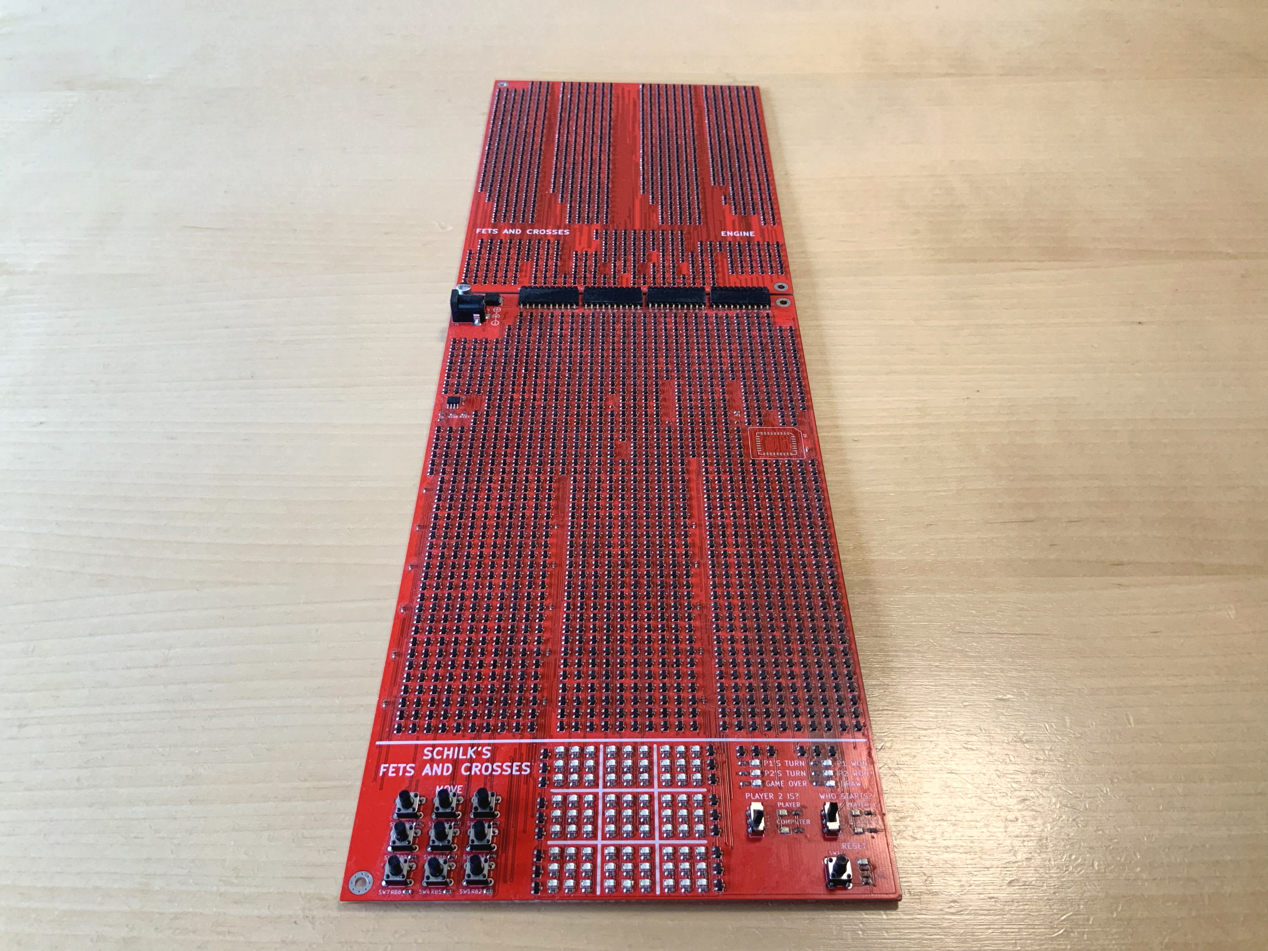
I split the design into two boards:
The main board contains the user interface, power regulation, a 555-timer based clock, and all logic except for the engine against which a player can play. There is a slot for a large FLASH memory, which, just as in the first iteration, can act as this engine. Alternatively the transistor-based engine, which is built on a separate PCB, can be connected to a series of pin-headers on the top.
The PCBs are both 2 layer, and the routing was done in a Manhattan style, with the top layer used for all transistor footprints and vertical routing, while the bottom layer was used for all horizontal routing:

A close-up of some of the routing on the main board.
Assembly
For some reason I decided to assemble these boards by hand. Did I mention that it took 3 revisions to get this all to work?
To make the process a little easier, I built a vacuum pick and place pen which allowed me to quickly transfer the components to the board directly from the reel. Since all transistors shared the same orientation on the board, this was actually a pretty quick process.
Here is a timelapse of one such assembly:
(Not included is me dropping the board from the solder hot-plate around 5 minutes after I stopped filming.)
Only after three revisions and once I had convinced myself that everything worked, did I spend the money to have five engines and main boards assembled: The uneven heating of the PCB during my manual soldering had introduced such significant warpage that my prototypes would break randomly after a few weeks due to tension breaking solder joints.
Gameplay Demo
Below is a quick video showing both me playing against myself in the player vs. player mode, and playing against the computer:
The Engine
Because Tic-tac-toe is such a simple game, implementing perfect play is rather straightforward.
In fact, you can think of the engine as a long if-else statement, that picks the first sensible
move:
if (b[top][left] == "us" && b[top][middle] = "us" && b[top][right] == "empty") {
  // can win in top row.
  play(top, right);
} else if (b[top][left] == "us" && b[top][middle] = "empty" && b[top][right] == "us") {
  // can win in top row.
  play(top, center);
} else if (b[top][left] == "empty" && b[top][middle] = "us" && b[top][right] == "us") {
  // can win in top row.
  play(top, left);
} else if ...
In fact, only 64 such checks are required to ensure the engine can never be beaten. In hardware, each one of these checks is implemented as a simple "decision gate", that activates its output if the particular situation it is hardwired to detect occurs. Once a decision gate fires, it blocks all subsequent decision gates from activating.
For example, the decision gate for the second if statement in the example above ("if in the top row, we have played the left and right cell, win by playing the center cell"), is implemented as follows:

An individual decision gate.
Note that because in CMOS it requires fewer transistors to build inverting logic (NOR and NAND gates),
the input signals to which the decision gates are connected are inverted (low if the condition is true).
The block input is connected to the previous decision gate and disables the gate from activating if
high. The block output is connected to the next decision gate, and is asserted if this or any previous
gate fires, locking subsequent gates.
The decision gates required, in order, are as follows:
- If it is possible to win by completing a row, win (9 gates)
- If it is possible to win by completing a column, win (9 gates).
- If it is possible to win by completing a diagonal, win (6 gates).
- If the opponent is one cell away of completing a row, block them (9 gates).
- If the opponent is one cell away of completing a column, block them (9 gates).
- If the opponent is one cell away of completing a diagonal, block them (6 gates).
- Prevent forks (3 gates).
- If the center is empty, play the center (1 gate).
- If the opponent has played in a corner and the opposite corner is empty, play in the opposite corner (4 gates).
- If a corner is empty, play in the corner (4 gates).
- If a side/top/bottom is empty, play there (4 gates).
Here a fork is a situation where the player has two possible slots to they can play to win against the engine. The precise decision required to prevent forks depends on the exact order of decision gates. For my implementation, the following suffices to completely prevent forks:
...
} else if (b[top][left] == "them" && b[bottom][right] = "them" && b[bottom][center] == "empty") {
  // prevent fork
  play(bottom, center);
} else if (b[top][right] == "them" && b[bottom][left] = "them" && b[bottom][center] == "empty") {
  // prevent fork
  play(bottom, center);
} else if (b[middle][right] == "them" && b[bottom][center] = "them" && b[bottom][right] == "empty") {
  // prevent fork
  play(bottom, right);
} else if ...
With this scheme, the 64 required decision gates and supporting logic (inversion of game state,
OR-ing of all play outputs for a specific cell) can be implemented using 1074 transistors, yielding
a fully combinational tic tac toe perfect play engine.
Full Engine Test

As a final step, I implemented a small STM32-based test bench that allows the engine to be connected to the PC. I also developed a small python script that plays every single possible game of Tic-Tac-Toe against the engine (there aren't that many!) and confirmed that the engine never loses.
Notes
In case it is not already obvious, efficiency and sensibility were not a top priority when
working on this project. I am sure there are more efficient flip-flop designs or
implementations with fewer transistors, especially by building composite gates that
combine NAND and NOR gates, but I don't really care :)