
This repo outlines the process for modding the NES to use 2 PPUs for advanced graphical features. I don't expect anyone to actually bother building this so the docs might be kind of half-assed at times. Check out my modified fork of Mesen2 if you'd like to play with this concept without modding your NES. See the related projects section for some demos that take advantage of the dual-PPU setup.
- More colors!
- More sprites!
- Parallax scrolling!

KiCad files can be found in the hardware directory.
You'll want to start with two consoles. One to modify and another as a parts donor.
| quantity | location | part number | description |
|---|---|---|---|
| 2 | U1, U2 | RP2C02 | PPUs desoldered from both consoles |
| 1 | U3 | AS6C6264-55PCN | Static RAM for PPU2 |
| 1 | U4 | 74LS373 | Address latch desoldered from donor console |
| 1 | U5 | 74LS139 | Demultiplexer desoldered from donor console |
| 1 | U1 | EMS-26405 | 40 pin wire wrap socket for PPU1 |
| 2 | J1 | 20 pin female pin headers to receive the wire wrap socket | |
| 1 | U5/J3 | 16 pin socket for 74LS139 | |
| 4 | RN1 | 10K 1/4 watt EXT pull down resitors | |
| 1 | 6x8cm prototype board | ||
| 1 | U2 | 40 pin socket for PPU2 (optional) | |
| 1 | U3 | 28 pin socket for AS6C6264-55PCN (optional) | |
| 1 | U4 | 20 pin socket for 74LS373 (optional) |
The 6x8cm prototype boards listed in the materials section is slightly too large and interferes with the expansion port.
- RP2C02 (U5) from the console you want to modify and your donor console.

- 74LS373 (U2) from your donor console.

- 74LS139 (U3) from your donor console.


These capacitors may be in the way of the dual-PPU board.

Fold them down flat or relocate them to the other side of the motherboard.

Solder 2 20 pin female headers where the PPU used to be.
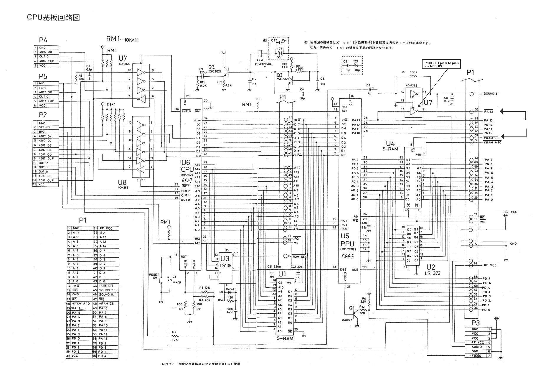
Follow the provided schematics and photos to assemble the dual-PPU board. Good luck.

remove pins 6, 7, 9, 10, 11, 12, 13, 14, and 15 from a 16 pin IC socket.
Bend pins 2, 3, 4, and 5 out horizontally.
Attach the socket on top of the console's 74LS139, soldering the remaining pins 1, 8, and 16.
Solder a jumper wire from pin 2 of the socket to CPU address line A12

Solder a jumper wire from pin 3 of the socket to the console's 74LS139 pin 5

Solder a jumper wire from pins 4 and 5 of the socket to the /CE pins of PPU1 and PPU2 respectively.
Install your donor 74LS139 in the socket.
Plug the dual-PPU board into the female pin headers. You're done.