Written by nyanpasu64
on
I recently purchased an ultra-cheap HDMI-to-VGA DAC to hook up my Nintendo Switch to my CRT monitor and external speakers. Unfortunately its audio out jack produced serious noise problems on my audio mixer, as well as my PC's mic jack. I spent several days diagnosing impedance issues, prototyping filtering for the delta-sigma audio DAC, and reworking PCB components to produce the best quality audio achievable with the hardware.
Prequel: Repairing my old HDMI DAC
Before buying the audio DAC, my initial plan for video was to plug my Switch dock into my ICY-Box HDMI-to-VGA DAC. While reworking my I2C bodge, I damaged several traces and lost components on the board, and had to reconstruct them by tracing the I2C lines in GIMP to learn their functionality. (The DAC's HDMI input is an I2C slave/peripheral, the SDA/SCL lines had high-impedance pull-up resistors to 5V which I omitted, and low-impedance resistors to the chip to pull the bus to ground.)
I took this as an opportunity to practice microsoldering with NH's recommended magnet wire and 3 second solder mask, before I used them for Switch modchip installation. The 36-gauge wire was helpful, as the enamel insulation was less prone to melting than Kynar, and the wire was thick enough to not snap easily while also thin enough to largely avoid ripping pads. The solder mask could cover exposed pads I didn't want to solder onto; I also used it to pin "finished" solder joints and wires in place while working nearby, though it proved to have poor adhesion to the PCB. Perhaps I needed to clean and roughen the surface more, or try YCS's 3 second mask instead of Relife?
- While tracing the PCB in my photos, I messed up several times by reading the PCB with the wrong orientation while flipping between the top and bottom. Next time I may use KiCad's reference photo functionality to model the PCB symbolically, rather than tracing traces with the GIMP pencil tool.
Hooking my Switch to my audio mixer
Surprisingly the hardest part of my setup was connecting my console to my external speakers. The ICY-Box DAC does not have audio out (as far as I can tell, the ITE IT6892FN chip does not output analog audio), while the Switch's headphone jack output annoying interference to my audio mixer and speakers. After hours of troubleshooting by unplugging and swapping out various cables and components, I eventually concluded that when the Switch is connected to a ground loop and not in sleep mode, its audio circuitry picks up 60hz hum and amplifies it into the output.
Asking online, I received a large number of suggestions, of varying levels of viability.
- Ground loop isolators use transformers to pass voltage offsets between circuit segments with separated grounds.
- I read that small ones tend to attenuate bass and other low-frequency signals, and large ones were expensive. Perhaps a cheap ground loop isolator is still worth considering?
- Converting my audio equipment to balanced differential audio can avoid ground loops; this is the approach taken by professional audio mixing consoles.
- However the equipment seemed expensive, and DI boxes often lower voltages to mic level (which seems counterproductive since it raises susceptibility to noise).
- Another option was HDMI audio extractors, but chaos (👋) told me every AliExpress HDMI-to-3.5mm or TOSLINK extractor it tried was poor quality, while audiophile products were expensive.
- In my research, most HDMI audio extractors are part of full bitstream receivers that also process the video signal. Perhaps it's just as expensive to only extract data islands and convert to analog or S/PDIF audio?
- Negative-feedback audio optoisolators have two receivers, and the LED is driven so both receivers' voltage matches the input voltage.
- I was dissuaded from using them by the 1BitSquared Discord server, but don't know why.
- I researched processing the ground and two audio signals as inputs to a differential amplifier. I abandoned the idea since I didn't know how to make it work with inputs outside the amp's supply rails, and it could have poor common-mode noise rejection.
The easiest workaround I found was to turn my Switch's volume jack to max (with the headphone volume limiter off) so game audio would be louder than ground loop hum, then turn down audio in my mixer. However I still had to plug and unplug the headphone jack every time I put my console in or out of the dock, and I worried about long-term damage to the console's audio amplifiers. I also tested an Apple USB-C audio dongle, but did not get audio out of it.
(I also experienced the same audio buzz with a "friend's" Switch 2 hooked up to my mixer, but at the time attributed it to my third-party HDMI dongle. As a sidenote, I will never buy a new Nintendo console after they sued Switch emulator developers, abusing their corporate legal budget to threaten independent developers with personal ruin over legally protected activity to pad their corporate coffers, and continue to issue GitHub takedowns against forks.)
The /crt/ Discord server recommended an AliExpress VGA dongle with 3.5mm audio output, which cost $2.58 plus shipping. (The price fluctuates slightly over time, and is currently sitting at $2.71 excluding a temporary 4th of July sale.) After the dongle arrived a week later, I plugged the VGA output into my video switch, connected the HDMI input to my Switch's video output, connected the audio output to my audio mixer... and heard the worst crackling I've ever heard come out of my Switch.
Confused, I connected it to my computer to capture audio through my motherboard's mic jack. I discovered a strange effect: the noise was almost inaudible when I set the Realtek audio's Mic Boost to off, but was overwhelming the usual sound when I turned it to +30 dB (even when I turned the volume down so game audio was at the correct volume). At this point I suspected the audio dongle was either pumping out ultrasonic harmonics, or its amplifier was distorting when changing mic boost changed my mic jack's input impedance.

To test the impedance theory, I measured the resistance between my motherboard's audio input and ground with my oscilloscope. Annoyingly the input pins had a constant DC offset of over 2 volts, which went away when shorted to ground but reappeared moments after I removed the short. This would eliminate any chance of properly measuring impedance. Undeterred, I measured resistance both ways and found that they measured open circuit one way and 300 ohms the other. Importantly, this measurement was unchanged by switching my Mic Boost levels. At this point, I would have to check for signal problems using my oscilloscope.
Probing the audio with my oscilloscope
I plugged the audio output into a breakout cable, and probed the exposed wire leads with my oscilloscope. There I found a startling 500-600 mV of noise covering the audio, with harmonics up to 50 MHz.


So I had confirmed the problem with the audio was ultrasonic DAC switching noise in the MHz range being modulated down to audible distortion by nonlinear amplifiers.
At this point I opened up my dongle to see what chip was inside. A photo revealed the chip was a NX3303X; I could not find any datasheets, but one Chinese website had a block diagram and pinout for the chip.

Searching around for other users of this chip, I found c0pperdragon (of Lumacode fame)'s HDMI2SCART project. This PCB uses chips largely harvested from AliExpress DACs like mine, and also hooks their audio output directly to speakers (through a DC-blocking cap yes, but with no treble filtering). Later I was told that he ran into the same audio issue as me, and had to add caps between the chip output and ground.
Browsing the repo's issue tracker, I ran into issue "Where to get NX3303X?" . This thread revealed that the MX9291 was another HDMI-to-VGA DAC chip with integrated audio out. While searching for NX3303X online, I also found a brochure for MX9291 saying this chip can replace the NX3303X and has a sigma-delta DAC, which suggests the NX3303X does as well. However the MX9292 (and 9291)'s pinout differs from the chip I had, so I did not further research it.

Building a lowpass filter
To fix audio playback, I'd have to design a lowpass filter to cut out the switching noise.
When designing a filter for signals, it's generally recommended to create Bode plots to show the filter's frequency response. I found a Bode plot generator which plots the exact curve by evaluating the filter's complex transfer function across a frequency sweep.
To simulate a first-order LPF (lowpass filter) with a cutoff of 50 kHz, I plotted 1/(1+s/50000) from frequency 10000000 (10 MHz) down to 10000 (10 kHz). Then we can check how much treble we lose at 20 kHz (the upper limit of ideal human hearing), and how much we suppress switching noise at 5-10 MHz (the DAC's approximate switching frequency).
- Sidenote:
sis canonically in imaginary radians/s, but we can pretend it's in cycles/s since transfer functions are unit-invariant.
Now that we've settled on a 50 KHz cutoff frequency, I started looking for convenient resistor and capacitor values to create this cutoff frequency. (Note that this would completely not work, for reasons that will be clear.)
To find the cutoff of a RC filter, we can use f = 1 / (2π RC). Plug into qalc:
> f = 50 kHz
> R = 31 ohms
> 1/(2pi R "C") = f

  C ≈ 102.6806084 nF
So we can add a 31 ohm resistor in series, followed by a 100 nF MLCC to ground. This runs into the problem that X7R ceramic capacitors convert vibrations into signals, but nobody cares this much about audio quality while gaming, and we have clock jitter to worry about too...
I reported my findings to an issue in the HDMI2SCART repo. The author soon replied back, saying he needed to add filter capacitors to block DAC noise. Interestingly, he found that without a filter resistor, a capacitance of 10 nF or even 1 nF was sufficient to block out switching noise. (Foreshadowing...)
Sidenote: Audio clock jitter
While probing filtered waveforms in my oscilloscope, I noticed considerable jitter in the period of the waves (despite them being an integer number of samples long in Audacity before playback). This meant the DAC's audio output had noticeable sample clock jitter, shifting samples back and forth in time relative to a "true" sampling rate of eg. 1 sample every 1/48,000 second.
Why does the jitter happen? I have no direct evidence, but some possibilities are:
- It stretches every blanking period's worth of audio samples over the next scanline, even when the number of samples is not constant.
- The DAC uses an unstable oscillator or PLL for timing sample output.
- The DAC is constantly adjusting its audio playback rate based on how many samples it's received from HDMI but not yet played.
- This would explain the occasional audio gaps I've heard; when the DAC plays samples too quickly and runs out of samples to play (an underrun), it has to wait for new ones to arrive.
My understanding is that to reduce jitter, it's best to regenerate a stable audio clock and keep it loosely in sync with audio arriving over TMDS blanking periods. I've found discussion of HDMI reclocking on audiosciencereview and such, but suspect much of it is snake oil.
In any case the jitter doesn't produce any audible issues for test tones or game audio, and the overall audio output is "good enough" to game on, though it also suffers from low volume and occasional audio gaps. I guess you get what you pay for in a $3 HDMI DAC.
Finding the switching frequency
At this point, largely out of curiosity I wanted to characterize the properties of my filtered audio signal. I'd start by finding the frequency of switching noise, to better understand the delta-sigma DAC and pick the best possible filter cutoff.

10, producing a square wave of period 76.8 ns and amplitude 175 mV. The filter reduces the oscillation to a quiet triangle-like wave.With the filter installed, you can actually see individual bits of the sigma-delta DAC output.
An incoming signal of silence would output a chain of 10 and 1100 symbols. By measuring the period of each high or low pulse in the delta-sigma signal, I estimated that each symbol was 37 ns long.
- Sidenote: the screenshot says the
10period was 76.80 ns long. If this is accurate, the symbols are actually 38.4 ns long. - The
10symbols produced a square wave at1/(37ns * 2) ≈ 13.5 MHz. (According to the oscilloscope, the frequency is1 / (76.8 ns) ≈ 13.02 MHz.)

1100 symbols, producing a longer period of 151 ns.- The
1100symbols produced a square wave at1/(37ns * 4) ≈ 6.76 MHz. (According to the oscilloscope, the frequency is1 / 151ns ≈ 6.62 MHz.)- Interestingly these frequencies are much lower than the 50 MHz I noted before. Perhaps the fast edges were signal reflections that are now hidden by the RC filter?
- If I sent non-silent audio to the DAC, it would output a non-uniform mixture of symbols. This would produce a non-periodic signal of intermediate spectral energy distribution.
Based on these numbers, we must maximize the attenuation at 5-10 MHz while retaining audible treble at 20 KHz. (A Reddit thread suggests 1 dB of change near 20 kHz is inaudible even to mastering engineers.)
While probing the circuit, I also noted down the voltages/amplitudes of the DAC output and filtered audio signal.
- The audio DAC's output was centered at 1.675 V, implying it was outputting a 50% duty cycle on a supply rail of 3.35 V.
- When playing a max-volume audio signal, the voltage swing was limited to about 50% of the way to {ground or 3.35 V}. This coincides with what I've read online about delta-sigma DACs having a practical 50% modulation depth before distortion becomes excessive.
- This meant the DAC could only output signals up to ±0.8375 volts relative to silence. This is enough range for loud audio sources, but licensed Switch games tend to have quieter audio, which may require turning up your speakers or mixers to compensate, or using the MasterVolume homebrew to raise the volume of Switch games.
- Unfortunately MasterVolume does not run at boot up, and you have to apply the audio volume every time you restart your console between emuMMC and sysMMC.
- The switching noise was gone from the output as expected, but surprisingly it was heavily attenuated before the filtering resistor as well!

Internal resistance
I decided to dig into this audio anomaly further by feeding my DAC square and sawtooth waves generated in Audacity. I started noticing some unexpected step responses.


I suspected the DAC couldn't supply enough current to drive a full-scale waveform through the filter. I tried reducing the gain in Audacity to -16 dB, but saw the same low-passed sawtooth wave with scooped troughs. This implied that the problem was not clipping (or current-limiting?), but likely a linear time-invariant lowpass that was far stronger than I intended or expected.
At this point I still thought that games sounded correct, and the problem must be synthetic test cases or a Windows audio processing effect. So I booted my Switch into L4T Ubuntu 24.04 to test the DAC on actual console hardware, but my square and sawtooth wave captures came out identically wrong.
As a final test, I tried playing the Wind Waker OST's Molgera theme on both my laptop and the HDMI DAC, feeding both to my audio mixer. The percussion was completely unrecognizable in the Switch's audio output, being muffled into near-oblivion compared to the reference audio.
I came to the realization that I built my low-pass filter wrong. The DAC could provide so little current that my filter cap's charge rate was bottlenecked on the DAC's internal resistance rather than my filter resistance!
Calculating the internal resistance through voltage and current
I was surprised the chip's output pin followed an exponential curve towards its intended smoothed voltage, suggesting an ohmic internal resistance. I had previously assumed the chip could force its DAC output to the nominal voltage as long as it's driving less than a maximum current, and would afterwards maintain a specific ΔV across the resistor to supply its maximum current.
Given that we can model the chip as a resistor (rather than a current-limited voltage source), I tried measuring the internal resistance two ways.
Voltage divider:
- The voltage before the filter resistor was actually the midpoint of a voltage divider between the chip's ideal "voltage source" and the comparatively fixed voltage of the filter cap. The voltage divider was composed of the chip's "internal resistance" followed by an external filter resistor.
- By measuring the voltage swing of the chip's output voltage, relative to the voltage swing of the ideal DAC, we can compare the external filter resistor to the total resistance (including internal).
- I saw a 175 mV swing on a PWM output from a nominal 3.3V source with midpoint 1.675 V (for actual voltage 3.35V). Feeding the voltage divider formula into qalc:
> 175 mV / 3.35 V = 33 ohm / (33 ohm + "Rint")

  ((175 millivolts) / (3.35 volts)) = ((33 ohms) / ((33 ohms) + Rint))

  Rint ≈ 598.7142857 Ω
RC filter time constant:
- I captured the defective audio output on my B550M DS3H motherboard audio interface at 192 kHz.
- Sidenote: MDFourier told me that playing and recording 48 kHz on this motherboard introduces some serious phase skew, and you need 96 kHz or higher for audio to round-trip through an analog cable. Though higher sampling rates are better for analyzing high frequencies anyways.

- It takes 8 samples (at 192000 smp/s) for the filtered square wave to move from one extreme to 0 volts before continuing. Therefore the half-life of the LPF is
8 smp / 192000 smp/s ≈ 41.667 us. - We can convert the half-life to a time constant using some tricky algebra. The time constant is
41.667 us / ln(2) ≈ 60.11 us.

In hindsight, how did I not notice a lowpass filter at 2.6 kHz for hours of gameplay? I did notice Splatoon 3 was more sizzly on Switch speakers than my DAC, but attributed it to the Switch's tinny speakers rather than my broken audio interface.
- Now convert the time constant into an internal resistance, knowing that our capacitance was 100 nF. Since the time constant =
RC:
> 60.11229337 us = ("Rint" + 31 ohm) (100 nF)

  Rint = 570.1229337 Ω
Phew that was a handful. We've now calculated the audio DAC chip's internal resistance two separate ways, ending up with values within 5% of each other. And the internal resistance positively dwarfs the resistance we intended for the RC filter. I reported my findings on the bug report thread.
Filtering with internal resistance
So we found out the chip has a lot of internal resistance. Adding extra resistance for the filter would further decrease its ability to drive audio loads. The best way I know to design a low-pass filter is to set R to our internal resistance and pick a C that produces the desired cutoff.
- This also explains why the PCB had no series resistors before the capacitors to ground; the PCB designers built filtering off the internal resistance, then the manufacturers skipped populating the filter caps to cut costs!
What's the ideal value of C for a lowpass filter? We can calculate how to achieve a 50 kHz cutoff frequency:
> 1 / (2pi 590ohm "C") = 50kHz
  approx. C = approx. 5.395082817 nF
It looks like 5.1 nF is a good value to pick. Higher capacitances will provide more filtering and a lower cutoff frequency.
The PCB already has an unpopulated footprint for a filtering capacitor from DAC output to ground. The footprint is 0402; we can squeeze in a 0603 capacitor but it'll be cramped and harder to solder, but a 0402 component is smaller and harder to hold. I haven't tried installing either on an unmodified board, and don't know which is easier to work with.
- I had already done some heavy PCB surgery to install filtering resistors. Since I did not have a 5 nF capacitor on hand, I instead bodged two 10 nF caps in series.
- When connecting capacitors in series, their leakage currents can be different and cause the voltage in between to drift. In this case it shouldn't exceed the DAC's DC offset of 1.675 V, and won't cause problems in practice.
One concern is that inexpensive X7R ceramic capacitors are microphonic and piezoelectric, so they convert environmental vibrations into changes in voltage, producing audible noises. C0G capacitors are non-piezoelectric and better for audio circuitry, but bulky and expensive to produce in large capacities. Luckily our 5 nF capacitance is small enough that LCSC sells 0402 C0G ceramics of this capacitance for a fraction of a penny.

DC blocking caps?
I also noticed that the DAC would create a pop whenever I plugged the audio cable into another device or unplugged it. This is because the manufacturers cut costs and replaced the DC blocking caps with 0 ohm jumpers, choosing to rely on the DC-blocking caps of the device receiving audio. (You also get a pop when you add or remove power, but this would happen even with caps present.)
I don't think there's an easy way to add DC-blocking caps. Assuming a 10 kohm load, you need 1 uF or so to pass bass at 20 Hz reasonably well:
> 1/(2pi 10 kohm "C") = 10 Hz

  approx. 'C' = approx. 1.591549431 uF
This large of capacitance is not easily available as C0G. The usual X7R MLCC capacitors are piezoelectric and will change voltage when bumped, which can add interference to audio. Electrolytic caps are an option, but will not fit well on pads meant for 0402 ceramics.
Additionally, if you didn't install a high-value resistor "outside" the DC-blocking caps to ground, the voltage between the audio source and sink's DC-blocking caps could again drift due to capacitor leakage. I've read that this can cause audio distortion that takes half an hour to begin, but could not find the website I read this on.
To fix this problem, you'd need to add extra resistors between the capacitor output and ground, which requires PCB modding since the designers didn't provide a footprint. All in all, this is a lot of bodge work for an end result that isn't even fully better than leaving out the DC-blocking caps like before.
Swapping the stereo channels
After playing some more Splatoon 3, I started to notice some nonsensical sound positions, like standing at the leftmost edge of a stage and hearing a massive explosion off-stage to my left. I started to suspect the audio DAC had swapped its audio channels, and managed to confirm this by positioning a training enemy to my left, making it shoot its gun, and hearing shot noises to my right.
To correct the audio placement, I'd have to swap the analog audio channels between the pins of my headphone jack. If I was designing the PCB, I'd swap the vias bringing the audio signals between the back and front of the board. But since I'm stuck with the layout of the board as is, I decided to cross-over the audio lines as they were running parallel across the board.
Looking through a cheap AliExpress digital microscope I scraped away the copper traces with an X-Acto knife, spraying isopropyl alcohol on the board to better see my work. Once the traces were severed, I scratched solder mask off the severed ends of the traces, fluxed and tinned the copper, and crossed the lines using 36 gauge magnet wire. After soldering on both wires, I cleaned off flux using a paper towel soaked in alcohol and a toothbrush, then embedded the wires in UV solder mask so they wouldn't rub against each other and short out or break off the board.
I checked in a multimeter that the traces were properly connected to the chip and not shorted, then fired up my game again. A quick test revealed that the stereo issue was fixed!
I do wonder how the designer and manufacturer of this PCB managed to screw up this badly. It's like neither one has actually meaningfully tested the audio section of this dongle to make sure it sounded correct on various devices, or had correct stereo imaging. It's like audio output was a box-ticking exercise rather than functionality they cared about...
Other hardware mods
In addition to these direct audio issues, I also ran into some other problems I wanted to address. For one thing, the VGA screws were too long, and would bottom out in the D-Sub sockets before it held the dongle tightly against the socket to prevent wobbling. I cut the screws shorter with a Dremel and sandpaper, but it took several rounds to fully resolve this issue, and (since I cut open the top to accommodate a heatsink, making the case less rigid) a good chunk of the wobble is still carried by the PCB rather than the plastic housing.
Another issue I noticed was chip overheating. After half an hour or so of use, the chip got so hot that I'd burn my finger touching the chip. Though I don't know the maximum safe temperature of the chip, I thought I could prolong the lifespan by attaching a heatsink (unlike my AliExpress MS2109 falsely sold as a USB3 device, which shorted out and turned into a cigarette lighter, though I don't know if that was from overheating or a silicon defect). I initially tried a mini heatsink with thermal adhesive from 2021, but it failed to adhere to the chip; I do not know if the glue has expired or the chip was too smooth, but I was not interested in sanding down the chip and risking mechanical damage to improve adhesion. I then tried old Arctic Silver 5 paste, wrapping a wire around the heatsink and PCB to apply pressure and adding hot glue to prevent movement; this worked but the heatsink tended to tip over if not mounted centered over the smaller chip.
Later I ordered double-sided thermal tape from AliExpress, and it took two weeks to arrive; I suspect my shipment got delayed because I ordered a UV lamp with a Li-Ion battery that got held up in customs. I cleaned off thermal paste from the chip and heatsink using isopropyl alcohol and a paper towel, then cut off a square of tape and stuck it to the chip. (I had to install the heatsink twice, the mating surface was larger than the DAC chip, and I think putting tape on the chip makes it easier to install the heatsink centered?)
In testing, the tape seems to conduct heat well enough (similar to thermal paste, though this is a low-power chip that only gets hot without active cooling). It also prevents the heatsink from shifting around and tipping over like with thermal paste. I did notice the heatsink would rotate (because the chip is smaller than my heatsink and the limited contact area provides minimal rotational stiffness), but the heatsink hasn't fallen off in use so far.
- Does the chip produce heat whenever it's receiving power, even when not generating video, because it's constantly switching voltage to produce a sigma-delta audio signal? I don't know enough about silicon thermal design to say, though I do know the RP2040 runs cool despite having a clock speed 10 times that of the audio DAC. Is the DAC outputting more power, despite its 600 ohms of internal resistance?
Another issue I had was the video signal cutting out when I bumped my desk; this turned out to be from not plugging in my HDMI splitter's USB cable all the way. I fixed the cable and have not seen the problem since. I did get another signal cutout when stepping under my desk, but this was because I accidentally knocked my Switch dock's power supply out of the power strip. The Switch is hard-coded to not output video unless it's receiving power, unlike every other battery-powered device that hooks up to a monitor, so Viture had to add an external power bank to their Switch dock designed for portable display glasses. Guess I'm a PC gamer at heart...
A Switch-specific issue was that I wanted to make my console output 720p to my CRT (because it cut off the edges of a 1080p signal and couldn't resolve the pixels), but 1080p to my LCD. On a computer you'd set it to output 720p to the CRT's identifier and 1080p to the LCD's identifier, but the Switch only has automatic and fixed resolutions. Automatic mode wouldn't help here, because the HDMI DAC edited my CRT's EDID data and added a 1080p resolution to the HDMI preset TV resolutions block, and I couldn't remove it by editing the monitor's original EDID.
To make the Switch see my CRT as 720p (from my 256B VGA EDID emulator), I cut the I2C lines off from the VGA and HDMI ports and bridged them with a wire; this worked, but left only two sync traces securing the bottom of the connector, and within a few weeks the joints broke off! That was a "fun" debugging session; the sync signals still made it to the connector when I pushed my oscilloscope probe against the pins, but disappeared when I wasn't checking.
Future: Second-order lowpass filter designs?
While simulating the circuit in Falstad's simulator, I found that it leaks up to ±20 mV of switching noise despite the optimal filtering of 5 nF.

I could raise the capacitor to 10 nF, but it lowers the cutoff frequency too far:
> 1 / (2pi 590ohm 5.1nF)
  ≈ 52.89296879 kHz

> 1 / (2pi 590ohm 10nF)
  ≈ 26.97541408 kHz
How much does a 27 kHz lowpass filter muffle treble? I fed 1/(1+s/26975) into the Bode plot generator, which showed my filter would attenuate 20 kHz signals to -1.9 dB. This was more treble loss than I was happy with.

Could I pick an intermediate capacitance? Maybe, it would reduce noise slightly more and also attenuate treble more than a 5.1nF cap.
To meaningfully improve audio quality, we need a second-order (or higher) filter. The simplest way to construct one is to cascade multiple RC sections, but this is challenging given we're already starting with 600 ohms of internal resistance. Moreover, cascaded RC sections are overdamped with poles to the left and right of each other in the s-plane, resulting in less noise reduction for a given amount of treble loss.
To construct a second-order Butterworth filter or similar, you need to use an inductor (for LC filter) or op-amp (for Sallen–Key filter). Large inductors are difficult to fit inside the dongle's shell. Sallen-Key lowpass filters only require resistors and capacitors, but I still wasn't interested in bodging extra filtering onto the existing PCB (whether by running wires and tacking components to their sides, or hot-gluing an op-amp upside-down to attach components to).
If we wanted to improve audio filtering, we could design a replacement PCB (four-layer for impedance matching and signal integrity?) with footprints and traces to install a second-order Sallen-Key filter. This would be about the same difficulty as the HDMI2SCART, but likely reusing the existing case and screws unlike the HDMI2SCART's 3D-printed case. We'd remove the DAC chip using hot air and transplant it onto the new board. If there was enough room, we could add electrolytic caps to block the DC offset.
- I'm not sure where to source straddle-mount VGA connectors. Alibaba has a product listing that describes the same part found in my DAC, but has no pictures of the actual product. I messaged them and they offered to send sample parts, but I did not follow up since I had no PCB to put the connector onto.
- In my experience straddle mount connectors are incredibly difficult to desolder even with Chipquik. It may be easier if you added hot air, though that risks melting nearby plastics.
- I also found straddle-mount VGA to break off the board easily, if you don't solder the shield onto the PCB (which the AliExpress dongle didn't).
- c0pperdragon reported that he sourced DAC chips by ordering VGA DACs online and desoldering them using hot air (though this adds extra cycles of heat stress).
All of this is possible... but it's a lot of work for an incremental upgrade that doesn't resolve the jitter and audio dropout problems. Compare this to the HDMI2SCART which required more manufacturing effort, but fulfilled a previously unmet use case; even then the author stopped selling them himself because he couldn't find a better source for chips.
What about other HDMI dongles?
Is there a better AliExpress device with correct stereo audio and capacitors on the the filtering pads (optionally installing DC blocking capacitors in place of the 0 ohm links)? I haven't found any so far.
- The HDMI2SCART chip sourcing thread shows a photo of a NX3303X-based PCB with a different layout, but it also omits the capacitors to ground (and presumably bridges the DC-blocking caps to cut costs). This PCB likely reverses the stereo channels as well, but I can't say for sure from a single-sided board shot.
- The /crt/ discord likes another NX3303X DAC located in an HDMI pigtail (rather than VGA output plug), but its PCB also has reversed stereo, missing filtering caps to ground, and 0-ohm resistors instead of DC-blocking caps (image, Discord, 2).
- At least this PCB has a lot of unused space, which would make it easier to mod and perhaps even add an op-amp.
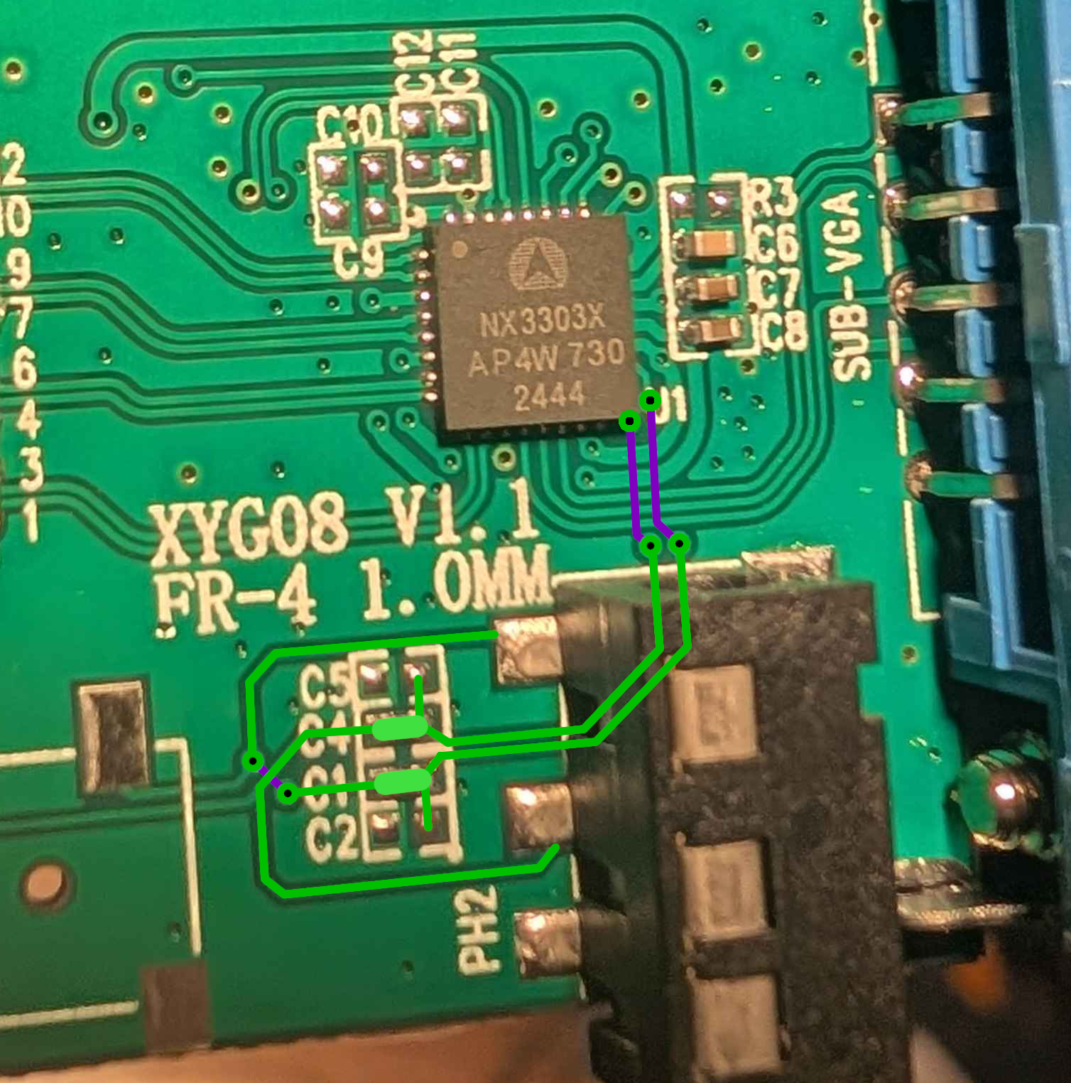
How did all 3 DACs reverse stereo audio? One theory I heard was that they copied each other's circuits without checking the datasheets or testing the stereo audio.
Which dongle would I recommend right now? I'd tentatively say the HDMI pigtail, since it's less prone to breaking connector pins than a dongle rigidly connected to a device; if you wanted to mod it you could presumably split the case in half, but I don't know how easy it is to add openings for a heatsink. You could also try a MX929*-based dongle, which may or may not have correct stereo channels (I cannot tell from the PCB photos I've seen, and both routing options are plausible).
In any case, if you can find a PCB with working audio filtering, let me know; this will help readers and the /crt/ community get better-quality audio from HDMI-based game consoles without painful modding work!