Introduction
If you’re tinkering around with embedded devices, having debug access is like having superpowers. It’s worth much more than having a firmware binary in my opinion, as it gives you the ability to step through code, analyze it dynamically, and understand it better. It can also help point you to code regions to analyze during static analysis. Many recent MCUs and SoCs allow manufacturers to restrict debug access, so getting debug access is a common attack vector. But what if you’re not able to reactivate debug access, or if the chip you’re analyzing doesn’t even have debug capabilities?
That’s what this blog article is about. I’ll discuss how instruction tracing of an external SPI flash helped me better understand the code flow of firmware running on a simple 8051 core.
I originally did this last summer during a group effort on the IoT Hacker Hideout Discord server, where people of different skill levels work together on the same devices. If you’re new to IoT hacking or want to improve your skills, I highly recommend joining the server. Originally, I used the Saleae Logic 8 Pro analyzer, which I’m a huge fan of, but the price point is a huge con for hobbyists. That’s why the new SLogic16U3 got my interest. I’ll use it during this article to test it and see if it fits my needs.
The Target
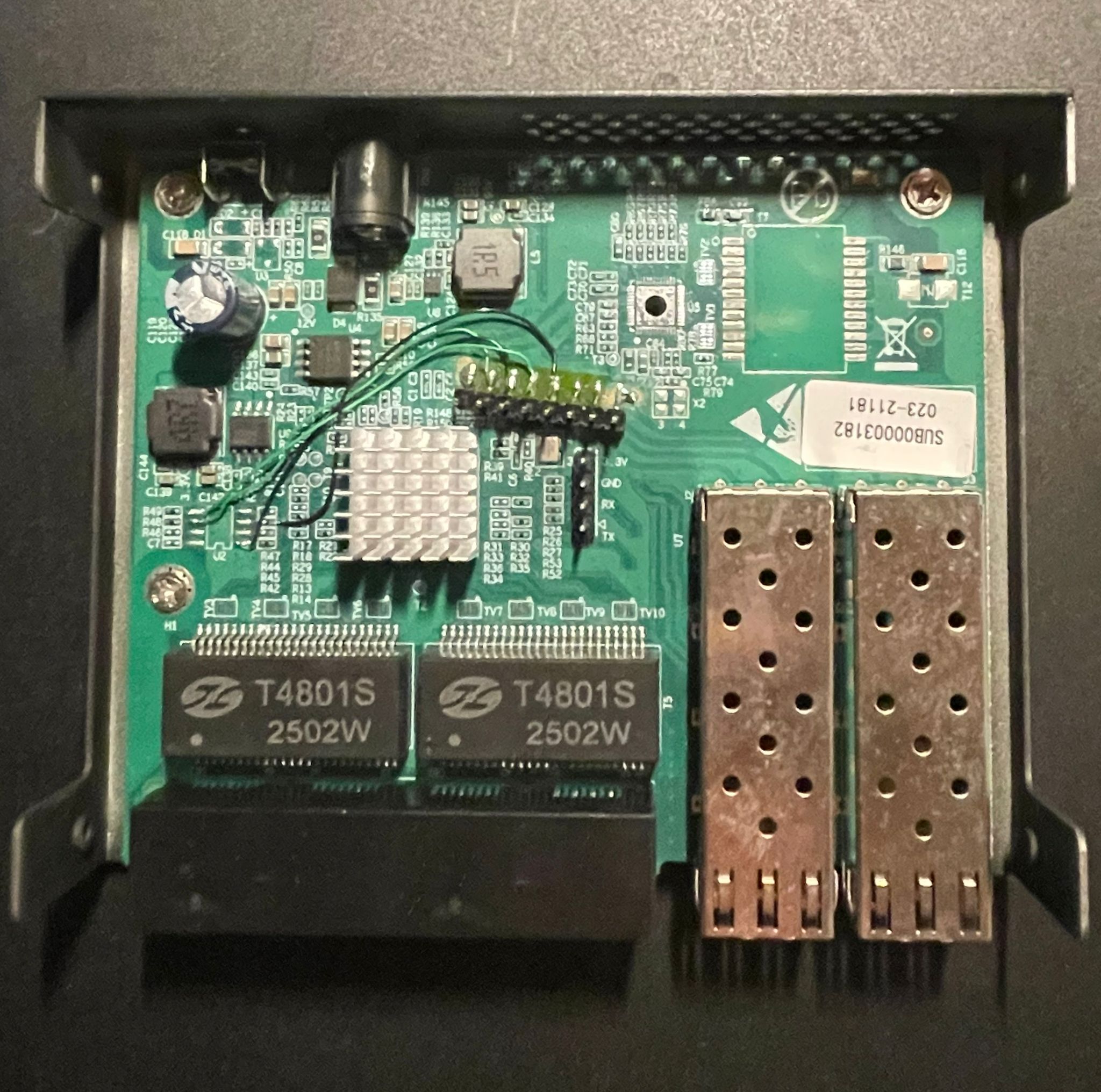
The target device is a cheap managed switch based on the RTL8372N. There are many of these devices on the market which all seem to be based on the same reference design and firmware SDK. The device we’re looking at is marketed by the company “GoodTop” as the “GT-ST024M”.
The RTL8372N is a Realtek network switch controller chip. It can be configured either through an external bus interface or via its onboard 8051 processor, which runs the management firmware and provides administrative web interface access to the switch. The firmware is located on an external QSPI Flash chip (W25Q16JV).

After opening the device enclosure, an unpopulated UART connector catches the eye of any interested hardware hacker. So let’s connect to it and repower the device:

Bummer. The UART console wants a password. Some research on the internet shows hardcoded passwords from preceding hardware versions, but none of them worked. Seems like they changed it. And with this, we found our target: let’s try to find the password.
Finding the Password
We don’t have access to an RTL8372N datasheet, but reading the ones for previous chips shows that they’re all very similar and mostly differ in their networking capabilities. None of them mention any hardware security, so it’s pretty clear that the password has to be somewhere in the flash.
Dumping the flash is no issue—it’s as easy as it gets using any adapter available. The flash contents are neither encrypted nor compressed, which makes sense since on such a system it’s expected to be using XIP (eXecute In Place), where the chip directly reads instructions it wants to execute from the flash into a buffer and executes them. This is unlike other systems where the firmware would be loaded into SRAM.
Using the strings command on the firmware dump reveals a lot of interesting details about the webserver itself, but nothing obvious hints us to the password. So we have to dig deeper, I guess.
For that, I like to use Ghidra. But there’s a catch: the 8051 architecture only has a 64KB address space. That’s way too small to have a webserver running with all its content. Therefore, it uses a mechanism called code banking
Code Banking: The 8051 extends beyond its 64KB limit by dividing code into multiple banks that share the same address space. A bank-switching mechanism (typically through Special Function Registers) selects which bank is currently visible to the CPU. This allows the firmware to access megabytes of flash memory by swapping banks in and out as needed. The first 16KB are for common functions and stay the same, while the next 48KB are for the individual banks.
This makes it extra painful to reverse engineer such firmware, especially as I have no prior experience with this architecture. Ghidra supports the 8051 architecture but not code banking. I was also able to find strings, but referencing them as usual did not work because of the banking. Although there are some efforts to implement it, like here and here, by the time I originally did this, these either didn’t exist yet or were not usable. Therefore, I wrote a loader script that takes the flash dump and loads it with overlays into Ghidra:

Still, there are all the different wrappers for bank switching which make reverse engineering annoying, especially since there are 21 banks in total.
So, is there any way to speed up the reverse engineering process? And here I had an idea: we don’t have debug access, but since the external flash is used with XIP, I could just sniff the QSPI communication and therefore find out the locations of the code that are executed. That way, I’m not able to create an actual code trace, but something very similar: a trace of instructions that are loaded from the flash for XIP. That should be very close.
Furthermore, I can create an instruction trace where the device is idle and another one where I type in a password. That way, I should be able to diff the two and get a hint of where in the firmware the password check logic or the password itself could be placed.
The Logic Analyzer
As mentioned earlier, I did this originally with a Saleae Logic 8 Pro, which I’m a huge fan of, but for some time I’ve been looking for a cheaper alternative that’s more in the budget of a hobbyist. Many of the cheaper analyzers won’t fit my needs as they’re too slow or require some unmaintained software. The software of the Saleae is actually the reason why I like them so much, as it’s actively maintained. Beginners often like to use the cheap Saleae clones, but I’ve had very bad experiences with them. Although they’re marketed with a 24 MHz sample rate, they didn’t capture the 8 MHz SPI communication of a project I was trying to debug. Took some time to figure that out back then…
Since the RTL8372N is using XIP, it has to get the instructions from the flash pretty fast, so the clock frequency is also pretty high. We need to be able to capture 60 MHz SPI. That’s why the SLogic16U3 is interesting. It claims to be able to have an 800M sample rate at 4 channels or 400M at 8 channels. It’s important to note that the SLogic16U3 has no internal memory, so it has to directly stream all data to the PC via USB 3.0. At the time of writing, there’s a bug in the Windows USB drivers that limits the maximum sample rate to 400M. Usually for practical digital sampling, we want 4× the clock frequency, so 400M will be more than enough.
To connect the logic analyzer to the flash chip, you can use SOIC clips. I’ve tried out several different brands, but for me, they all get chewed up after some time and don’t stay in place anymore. That’s why I placed some additional pin headers on the PCB to have solid connections to the flash, as I was planning to tinker around with it much more.

Sniffing the Flash
Let’s start sniffing. I used the custom version of PulseView by SiPeed as their driver is not upstream yet. It works just like general PulseView, which has its quirks.
I named all four channels for later analysis, powered on the switch, waited until it booted and the password screen appeared on UART, and then started a capture with 4 channels at 200 MHz sample rate and 500M samples. That’s about 2.5 seconds and enough.

As you can see in the screenshot, I was almost ready to move to the next step. Luckily, PulseView already has a working analyzer for SPI Flash. For Saleae Logic, I had to implement the fast read command for its community protocol analyzer (PR here).
The only problem with it: its performance. It’s painfully slow, especially since we have such a high amount of samples. For this trace, it took 15-20 minutes and allocated 8GB of RAM. But still, it worked. Afterwards, exporting the analyzed memory commands into a text file was straightforward:
64875-65369 SPI flash/EEPROM: Commands: Fast read data (addr 0x020fe2, 14 bytes): 7f 74 7e 78 12 31 5b e4 fb fa f9 f8 c3 12
65403-77378 SPI flash/EEPROM: Commands: Fast read data (addr 0x096aad, 211 bytes): ab 07 aa 06 e4 ff fe fd fc 90 1d 33 12 1a c9 e4 ff fe fd fc 90 1d 2f 12 1a c9 ea f5 a2 eb f5 a3 75 a0 01 af a1 ef 70 fb af a4 fc fd fe 90 1d 33 12 1a c9 90 1d 2f 12 1a 5f c0 00 90 1d 33 12 1a 43 78 18 12 19 e0 d0 00 12 19 71 90 1d 2f 12 1a c9 af a5 e4 fc fd fe 90 1d 33 12 1a c9 90 1d 2f 12 1a 5f c0 00 90 1d 33 12 1a 43 78 10 12 19 e0 d0 00 12 19 71 90 1d 2f 12 1a c9 af a6 e4 fc fd fe 90 1d 33 12 1a c9 90 1d 2f 12 1a 5f c0 00 90 1d 33 12 1a 43 78 08 12 19 e0 d0 00 12 19 71 90 1d 2f 12 1a c9 af a7 e4 fc fd fe 90 1d 33 12 1a c9 90 1d 2f 12 1a 43 90 1d 33 12 1a 5f 12 19 71 90 1d 2f 12 1a c9 90 1d 2f 12 1a 43 22 90 19 17 ee f0 a3
77412-78095 SPI flash/EEPROM: Commands: Fast read data (addr 0x020fe9, 21 bytes): e4 fb fa f9 f8 c3 12 19 bc 7f 00 60 02 7f 01 22 90 16 ed 12 1b
78129-78479 SPI flash/EEPROM: Commands: Fast read data (addr 0x034018, 8 bytes): ef 64 01 60 03 02 40 db
78513-78959 SPI flash/EEPROM: Commands: Fast read data (addr 0x0340db, 5 bytes): 22 78 3d e6 54
78993-79830 SPI flash/EEPROM: Commands: Fast read data (addr 0x0350e7, 22 bytes): 90 aa 1b 12 1a 43 ef 54 01 ff e4 fe fd fc ef 70 03 02 51 9a 90 aa
79863-80418 SPI flash/EEPROM: Commands: Fast read data (addr 0x03519a, 16 bytes): 90 aa 13 12 1a 43 ec 33 40 15 90 aa 13 12 1a 43
80452-80742 SPI flash/EEPROM: Commands: Fast read data (addr 0x0351b9, 6 bytes): 12 48 4a ec 4d 4e
80775-81487 SPI flash/EEPROM: Commands: Fast read data (addr 0x03484a, 22 bytes): 90 aa 1b 12 1a 43 ef 54 01 ff e4 fe fd fc ef 70 02 ff 22 90 aa 29
81521-81871 SPI flash/EEPROM: Commands: Fast read data (addr 0x0351bd, 8 bytes): 4d 4e 4f 60 1e 90 aa 5e
....
Next, I did the same while typing in a wrong password, so I had two trace files.
Analyzing the Traces
To make sense of these traces, I vibe coded a Python script to convert raw flash addresses into the 8051 banked memory format and provide various analysis modes. The script needed to:
- Convert flash addresses to banked addresses
- Show execution traces
- Show unique addresses (coverage)
- Optionally display read lengths and data bytes
- Support ASCII representation of data
Here’s the analysis script:
import sys
import argparse
import re

def flash_to_banked(flash_addr):
    """Convert raw flash address to 8051 banked memory format

    Memory layout:
    - 0x0000-0x3FFF: Common code area (not banked)
    - 0x4000+: Banked area, each bank is 0xC000 bytes
      Bank pages map to 0x4000-0xFFFF in CPU address space
    """
    # Common code area (not banked)
    if flash_addr < 0x4000:
        return f"CODE::{flash_addr:X}"

    # Banked region
    # Flash offset from start of banked area
    flash_offset = flash_addr - 0x4000
    bank = (flash_offset // 0xC000) + 1
    # Offset within the bank, mapped to 0x4000-0xFFFF
    bank_offset = (flash_offset % 0xC000) + 0x4000

    return f"BANK_{bank}::{bank_offset:X}"

def parse_addr(addr_str):
    """Parse hex address string to int"""
    return int(addr_str.replace('0x', ''), 16)

def hex_to_ascii(hex_string):
    """Convert hex string to ASCII representation
    Non-printable characters are shown as '.'
    """
    # Remove spaces and convert to bytes
    hex_clean = hex_string.replace(' ', '')
    try:
        ascii_chars = []
        for i in range(0, len(hex_clean), 2):
            byte_val = int(hex_clean[i:i+2], 16)
            # Use printable ASCII (32-126), otherwise use '.'
            if 32 <= byte_val <= 126:
                ascii_chars.append(chr(byte_val))
            else:
                ascii_chars.append('.')
        return ''.join(ascii_chars)
    except:
        return ''

def format_address(addr_str, mode, length=None, data=None, show_ascii=False):
    """Format address based on mode: flash, banked, or both"""
    try:
        flash_addr = parse_addr(addr_str)
        length_str = f" ({length} bytes)" if length else ""
        data_str = ""

        if data:
            data_str = f": {data}"
            if show_ascii:
                ascii_repr = hex_to_ascii(data)
                data_str += f" | {ascii_repr}"

        if mode == 'flash':
            return f"{addr_str}{length_str}{data_str}"
        elif mode == 'banked':
            return f"{flash_to_banked(flash_addr)}{length_str}{data_str}"
        else:  # both
            return f"{addr_str} -> {flash_to_banked(flash_addr)}{length_str}{data_str}"
    except:
        return addr_str

def parse_line(line):
    """Parse a line in format: 'timing Fast read data (addr 0xXXXXXX, N bytes): data'
    Returns (address, length, data) tuple or None if not a valid line
    """
    # Pattern: addr 0xXXXXXX, N bytes): data
    pattern = r'addr\s+(0x[0-9a-fA-F]+),\s+(\d+)\s+bytes\):\s*(.+)$'
    match = re.search(pattern, line)

    if match:
        addr = match.group(1)
        length = int(match.group(2))
        data = match.group(3).strip()
        return (addr, length, data)

    return None

def analyze_trace(input_file, show_mode, format_mode, show_length, show_data, show_ascii):
    """Analyze trace from line-based format file"""
    addresses = []

    with open(input_file, 'r', encoding='utf-8') as f:
        for line in f:
            result = parse_line(line)
            if result:
                addr, length, data = result
                if not show_length:
                    length = None
                if not show_data:
                    data = None
                addresses.append((addr, length, data))

    if show_mode == 'unique':
        # Get unique addresses and sort (coverage)
        seen = {}
        for addr, length, data in addresses:
            if addr not in seen:
                seen[addr] = (length, data)
        addresses = [(addr, seen[addr][0], seen[addr][1]) for addr in sorted(seen.keys(), key=parse_addr)]

    return [format_address(addr, format_mode, length, data, show_ascii) for addr, length, data in addresses]

def main():
    parser = argparse.ArgumentParser(
        description='Flash Trace Analyzer - convert raw flash addresses to 8051 banked memory format',
        formatter_class=argparse.RawDescriptionHelpFormatter,
        epilog="""
Examples:
  %(prog)s trace.txt                    # full execution trace (default)
  %(prog)s trace.txt -m unique          # unique addresses (coverage)
  %(prog)s trace.txt -l                 # trace with read lengths
  %(prog)s trace.txt -d                 # trace with data bytes
  %(prog)s trace.txt -d -a              # trace with data bytes and ASCII
  %(prog)s trace.txt -l -d              # trace with lengths and data
  %(prog)s trace.txt -m unique -l       # coverage with read lengths
  %(prog)s trace.txt -f flash           # execution trace as raw flash addresses
  %(prog)s trace.txt -m unique -f both  # coverage with both formats

Input format:
  Lines should contain: "addr 0xXXXXXX, N bytes"
  Example: "64875-65369 SPI flash/EEPROM: Commands: Fast read data (addr 0x020fe2, 14 bytes): 7f 74..."
        """)

    parser.add_argument('input_file', help='Input file with lines containing "addr 0xXXXXXX, N bytes"')
    parser.add_argument('-m', '--mode', choices=['unique', 'trace'], default='trace',
                       help='Analysis mode: unique (coverage) or trace (execution order) (default: trace)')
    parser.add_argument('-f', '--format', choices=['flash', 'banked', 'both'], default='both',
                       help='Output format: flash (raw), banked (8051), or both (default: both)')
    parser.add_argument('-l', '--length', action='store_true',
                       help='Show read length in bytes')
    parser.add_argument('-d', '--data', action='store_true',
                       help='Show data bytes that were read')
    parser.add_argument('-a', '--ascii', action='store_true',
                       help='Show ASCII representation of data (requires -d)')
    parser.add_argument('-o', '--output', help='Output file (default: print to console)')

    args = parser.parse_args()

    # ASCII requires data flag
    if args.ascii and not args.data:
        print("Warning: -a/--ascii requires -d/--data flag, enabling data output", file=sys.stderr)
        args.data = True

    try:
        results = analyze_trace(args.input_file, args.mode, args.format, args.length, args.data, args.ascii)

        if not results:
            print("Warning: No valid addresses found in input file", file=sys.stderr)

        output = '\n'.join(results)

        if args.output:
            with open(args.output, 'w') as f:
                f.write(output + '\n')
            print(f"Written {len(results)} addresses to {args.output}")
        else:
            print(output)

    except FileNotFoundError:
        print(f"Error: File '{args.input_file}' not found", file=sys.stderr)
        sys.exit(1)
    except Exception as e:
        print(f"Error: {e}", file=sys.stderr)
        sys.exit(1)

if __name__ == '__main__':
    main()
This script enables me to turn the raw traces into a cleaner log that looks like this:
0x020fe2 -> BANK_3::8FE2 (14 bytes)
0x096aad -> BANK_13::6AAD (211 bytes)
0x020fe9 -> BANK_3::8FE9 (21 bytes)
0x034018 -> BANK_5::4018 (8 bytes)
0x0340db -> BANK_5::40DB (5 bytes)
0x0350e7 -> BANK_5::50E7 (22 bytes)
0x03519a -> BANK_5::519A (16 bytes)
0x0351b9 -> BANK_5::51B9 (6 bytes)
0x03484a -> BANK_5::484A (22 bytes)
0x0351bd -> BANK_5::51BD (8 bytes)
0x0351e0 -> BANK_5::51E0 (16 bytes)
0x0b2c48 -> BANK_15::AC48 (51 bytes)
0x096aad -> BANK_13::6AAD (211 bytes)
0x0b2c73 -> BANK_15::AC73 (38 bytes)
0x049190 -> BANK_6::D190 (96 bytes)
0x04928d -> BANK_6::D28D (19 bytes)
0x0491ab -> BANK_6::D1AB (5 bytes)
.....
Inside this log file, there’s a pretty obvious repeating pattern, so there seems to be some kind of loop running that probably also waits for password input. I used the unique mode on both log files and compared which addresses appeared in the trace where I typed in the wrong password that weren’t in the idle trace.
This gave me dozens of locations in code that I then looked up in Ghidra:
Addresses in file2 but not in file1:
0x03a762 -> BANK_5::A762
0x03a782 -> BANK_5::A782
0x03a77a -> BANK_5::A77A
0x03a768 -> BANK_5::A768
0x04886d -> BANK_6::C86D
0x03a76e -> BANK_5::A76E
0x03a773 -> BANK_5::A773
0x03a77f -> BANK_5::A77F
0x0747ed -> BANK_10::87ED
0x03a774 -> BANK_5::A774
0x03a76f -> BANK_5::A76F
0x04891c -> BANK_6::C91C
0x03a77e -> BANK_5::A77E
0x0488a7 -> BANK_6::C8A7
0x03a776 -> BANK_5::A776
0x03a779 -> BANK_5::A779
0x04884e -> BANK_6::C84E
0x03a765 -> BANK_5::A765
0x03a778 -> BANK_5::A778
0x03a76a -> BANK_5::A76A
0x03a781 -> BANK_5::A781
0x075a0a -> BANK_10::9A0A
0x0ac070 -> BANK_15::4070
0x0488b7 -> BANK_6::C8B7
0x048893 -> BANK_6::C893
0x048888 -> BANK_6::C888
0x03a77b -> BANK_5::A77B
0x03a76b -> BANK_5::A76B
0x03a77d -> BANK_5::A77D
0x03a770 -> BANK_5::A770
0x0488b2 -> BANK_6::C8B2
0x03a771 -> BANK_5::A771
0x03a763 -> BANK_5::A763
0x03a775 -> BANK_5::A775
0x03a766 -> BANK_5::A766
0x03a76c -> BANK_5::A76C
0x03a764 -> BANK_5::A764
0x074753 -> BANK_10::8753
0x07476d -> BANK_10::876D
0x03a77c -> BANK_5::A77C
0x03a769 -> BANK_5::A769
0x03a780 -> BANK_5::A780
0x03a772 -> BANK_5::A772
0x03a76d -> BANK_5::A76D
0x04881a -> BANK_6::C81A
0x048919 -> BANK_6::C919
0x048876 -> BANK_6::C876
0x03a767 -> BANK_5::A767
0x03a777 -> BANK_5::A777
0x07ffff -> BANK_11::7FFF
That’s when I had an idea and added a feature to my script to show me the loaded data in ASCII representation. And sure enough, I was able to see that the @@@@@@@@@Key is wrong@@@@@@@@@ string was loaded from the flash. So I looked at what addresses were loaded before that.
In Ghidra at BANK_10::87ED, I found what looked like a command parser pretty quickly.

This code XOR-decrypts 11 bytes of user input, compares them against a stored password (that is saved in its XORed representation in DAT_EXT_1755), and if successful (plus some additional flag checks), grants access.
Reading the Password
Now that we know the password is located at DAT_EXT_1755, we want to read it out. On the 8051, DAT_EXT refers to external memory. In our case, this external memory is actually outside of the core but inside the chip. It acts like additional SRAM. This also means that the encrypted password gets written there during early bootup or initialization. We could try to find this loading using static analysis, but remember that I’m not comfortable reverse engineering this firmware, and I want to demonstrate a more dynamic approach.
One could just run a debugger and read the address in it, but remember, we don’t have debug access. However, there’s a workaround: we have control over the flash. If we modify the firmware, we can just write a small gadget that dumps the 11 bytes at DAT_EXT_1755 on UART.
Let’s write a print-out gadget in assembly:
MOV DPTR, #0x1755    ; 90 17 55 - Point to start address
MOV R6, #11          ; 7E 0B    - Loop counter (11 bytes)

loop:
MOVX A, @DPTR        ; E0       - Read byte from external memory
MOV R7, A            ; FF       - Move to R7 (print function parameter)
LCALL 0x3bed         ; 12 3B ED - Call print function
INC DPTR             ; A3       - Move to next address
DJNZ R6, loop        ; DE FC    - Decrement counter and loop if not zero
This gadget iterates through 11 bytes starting at external memory address 0x1755. For each byte, it reads the value into the accumulator, transfers it to register R7, and calls a print function at CODE:0x3bed that outputs the value to UART. The DPTR register is incremented after each iteration, and the loop counter in R6 ensures exactly 11 bytes are printed before the loop terminates.
Compiling the Gadget
To compile this assembly code into binary form, we can use the SDCC (Small Device C Compiler) toolchain. The process involves assembling the source file, linking it, and converting the output to raw binary:
# Assemble the code (creates .rel object file)
sdas8051 -losff shellcode.asm

# Link to Intel HEX format
sdld -i shellcode.ihx shellcode.rel

# Convert Intel HEX to raw binary
sdobjcopy -I ihex -O binary shellcode.ihx shellcode.bin
The assembled binary can then be inserted into the firmware at an appropriate location, such as where the branch to the password check function would be. We don’t care if we crash the firmware afterwards, as long as it dumps the password first.
Injecting the Gadget
But there’s another catch: during bootup, there’s a checksum check. It checks both the “header checksum” and “payload checksum”. I’m not sure which exact addresses are considered “payload,” but if you change any code, the checksum check will probably fail.
You can display the header in the SPI viewer mode by pressing v during bootup. The header is also located at 0x1D000 in the dump. The checksum is just a simple sum algorithm (all data gets summed). Let’s say you change some data in the firmware, like changing JNZ to NOP: 70 21 => 00 00. Now you have to subtract the changes from the payload checksum. In this case, we have to subtract 0x70 + 0x21 from the checksum. So 0x04429177 => 0x044290e6. We have to write the new payload checksum in the header at 0x1D00C. But now we’ve changed the header, so we also need to change the header checksum. I wrote a tiny Python script for that:
import struct

# Header values
magic_number = 0x12345678
length = 0x000e320c
payload_checksum = 0x44290e6
reserved = 0x332255ff

# Pack as binary data and sum bytes
data = struct.pack('>IIII', magic_number, length, payload_checksum, reserved)
header_checksum = sum(data) & 0xFFFFFFFF  # 32 bit overflow

print(f"Calculated Header Checksum: 0x{header_checksum:08x}")
Output for the new header checksum will be 0x000004c5. We write this value to 0x1D008.
Now you should be able to boot and pass the checksum check. After flashing the modified firmware, the device boots, our gadget runs, and the XORed password bytes are dumped to UART. We can then XOR them with 0x5a to recover the plaintext password:
The password is Lx+2035&asp
Looking for the password in the flash dump it turns out that it is located at CODE:3e88 XORed with 0x5a, and it gets checked at BANK_10::87ca.
Conclusion
This project demonstrates that even without debug access, creative hardware-level techniques can provide valuable insights into firmware behavior. By sniffing the SPI flash bus, I was able to create an instruction trace that led me directly to the password validation logic.
I’ll be honest: I’m probably not the best reverse engineer, and a more skilled person might have solved this purely through static analysis. At the time I started this, I wasn’t even fully understanding how the banking mechanism worked. I was working in a team environment and wanted to get results quickly, so I tried to achieve the goals with the techniques I knew best: hardware analysis and dynamic observation.
This was also my first experiment with the SLogic analyzer, and so far I’m pretty happy to finally have a low-cost capable hardware device for my hobby projects. The Saleae Logic is simply too expensive for hobby use, but I do wish the PulseView software had better performance. Since there’s a PR to get the SiPeed driver upstream, I’m confident that I’ll benefit from ongoing PulseView development rather than being stuck with some fork, as is the case with other logic analyzers that have appeared on the market.
Overall, instruction tracing via SPI flash sniffing proved to be an effective technique when traditional debugging methods aren’t available. It’s another tool in the hardware hacker’s arsenal for understanding embedded systems.